A little while ago I picked up an AD9850 DDS board. Basically, these are little boards you can pickup on eBay for about $10 shipped that can be programmed to output a sinusoidal wave from 1hz to about 40mhz. The output is about 1Vp-p and is fairly clean.
To drive these little boards you have to program them using either a serial interface or a parallel interface. You send over a couple of bits according to a code specified in the spec sheet and the AD9850 outputs the appropriate frequency.
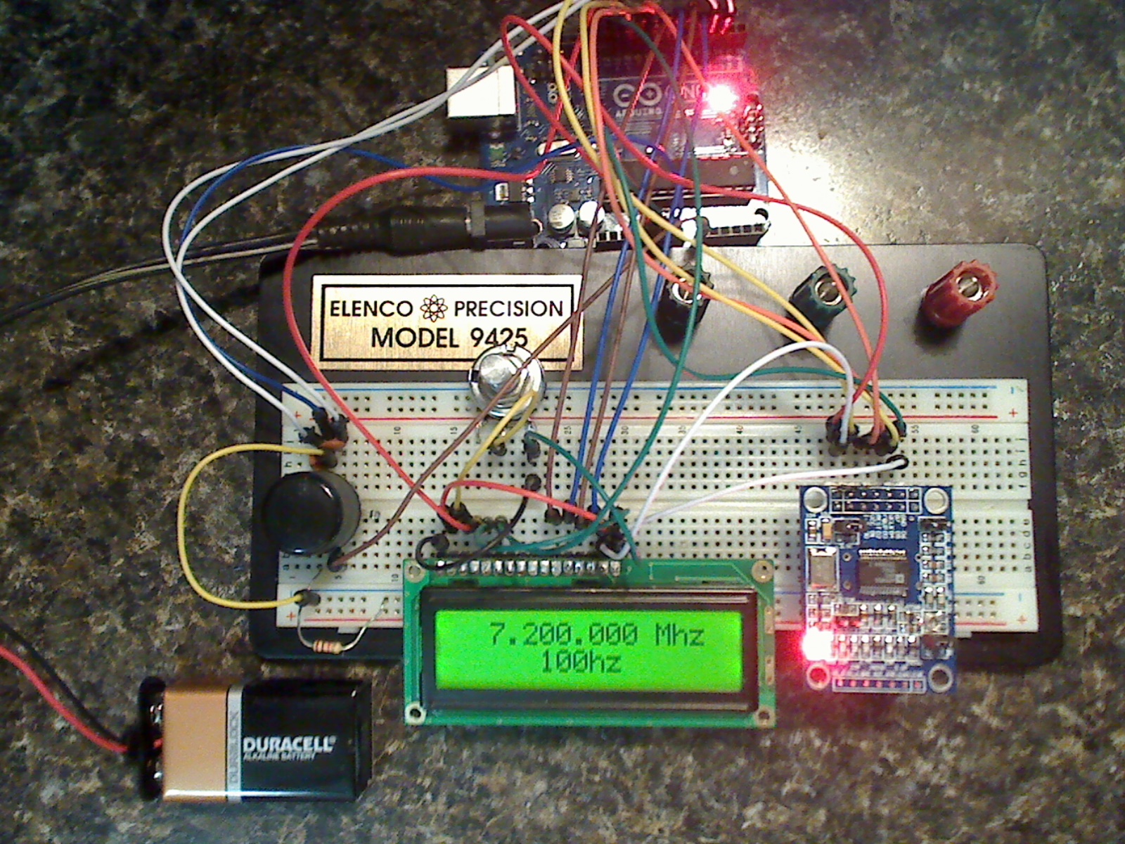 I used an Arduino UNO board, LCD 16×2 display, and a rotary encoder to create a little all-in-one VFO. It can output the full range available to the AD9850 but I simply limited it to only 7.0-7.3Mhz in the Arduino code. I will be using the VFO as part of a DC receiver I am putting together for fun.
You can see a video of it in action here: http://youtu.be/r6nRMikOOmI
The code to drive the AD9850 is fairly simple, however, the hardest part I found was getting the large integer (frequency) split up into the appropriate numbers to display on the LCD screen. Some creative code fixed that problem. Full documents and discussion on this item is on the permanent page located here.
I would like to thank you for a lot of hard work, I was able to modify the code for my use easily. this is a great start for my 40 meter qrp cw transceiver.
Thank you for putting this together.
N5ZKZ
I am building the AD9850 DDS VFO. I just got all the parts together.
I have seen other AD9850 VFOs with two 1k resistors on switches to ground.
Why do you use a 1k and a 100 ohm resistor? The 100 ohm resistor is a problem for me but I have a lot of 1k s.
Thanks Rich w6du
100ohm was only because it was next to me on the bench. 100ohm, 470ohm, 1k, 1.8k, and other similar values will all work. It is just important that you use one so you do not pull to much current through the Arduino when you set the switch to ground. 10K is probably the highest I would use. It’s all about sensing the voltage drop (to 0v) and not the current.
Rich
AD7C
very nice….
This is really interesting. I will be building this too once I got the parts from Amazon. But I wonder if this can be used to replace the faulty DDS board of the Kenwood TS-850S? Has anyone thought about this? I know some people who had this problem of the first batch of the faulty DDS chips and they are still hoping that they can find a new DDS board although you can not find this anymore in the market. Perhaps someone can have a look if its feasible?
Thank you and 73,
Max DV2UXH
Hello Rich ,
Thank you very much, very nice project.
I start learn Arduino with your project. (Nano and 9850 DDS).
73 TNX
Luis LU1AGP
Can you please help me, I am very new to programming Arduino software and I am trying to build the AD9850 VFO but always get “rotary.h no such file or directory. I have tried every thing to get it to work without any success. I note from one of the comments that your answer was did you import the file properly, but I do not know how to do that. Is it possible to point me in the right direction I have tried Arduino CC but can not find any solution. I must admit I not skilled in this programming but desperate to get it to work and would really appreciate any help or guidance you can give me.
FIrst. Try this.
Regarding the “rotary.h not found” error, the problem is not actually with importing the library.
The library defines the file as “Rotary.h”. The code includes the line “rotary.h”.
The solution is is simple: capitalize the “R”. Then the code compiles nicel
If not… Look through the comments. Asked and answered many times.
-Rich