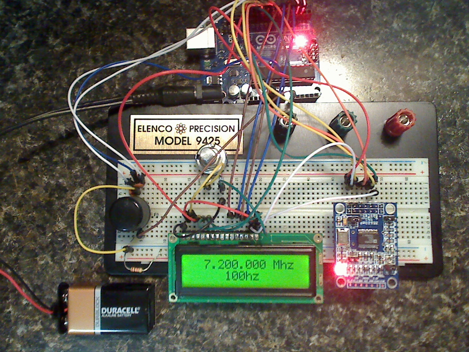
A lot of people have been contacting me about my Arduino and AD9850 VFO project. I never knew DDS VFO’s were so popular! Go figure? Anyways… I digress!
A couple of days ago Dave (WB4CHK) contacted me with a few questions. He was on a quest to build a daughter-card that would plug in as a shield to the UNO. After a few back-and-forth items Dave finished his project. Rather than let me explain I’ll just post what he sent me below:
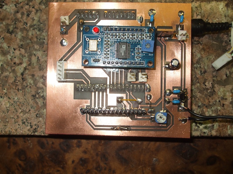
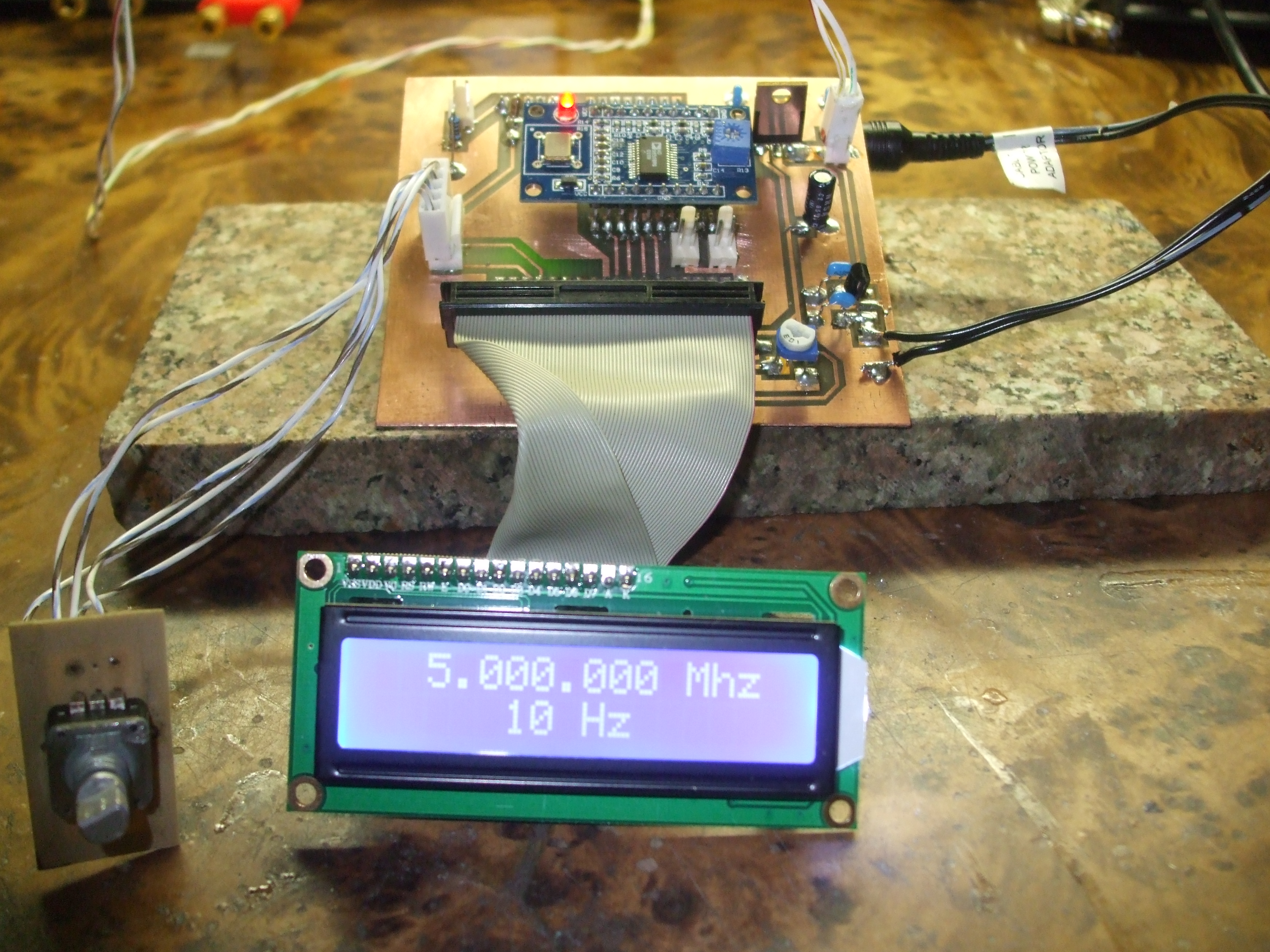
Hi Rich: I finished the Sig Gen board and it works great. The board plugs into the UNO, I hate batteries so I added a 5 volt regulated supply for the board and a 9 volt regulated supply for the UNO. Might be overkill but I can hook it up to my 12V+ bench supply and run all day. The outputs are the two 2pin connectors just below the 9850 module. The one on the right is sine wave the one on the left is connected to the square wave output (if it is ever added).
He also sent over a few photos of the finished unit. Pretty cool! Note: You won’t see the Arduino in any pics but it’s there. In fact, it’s underneath the board in the 3rd picture.
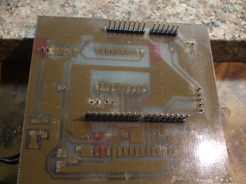
Dave has been so nice as to also provide the design and schematics he used to create his PCB. You can download the PCB design’s here. Using a laser printer and the toner-transfer method you should be able to duplicate Dave’s work. If you have any questions Dave gave me permission to post his email so go ahead and send him a note: Davewb4(at)aol.com. Obviously replace the (at) with the @ and you’re on your way.