
I was browsing eBay one day and I ran across a posting for the Analog Devices AD9850. The AD9850 is a chip that can produce a sinusoidal wave from about 1hz to 40mhz. Somehow the electronics dealers in Hong Kong have been able to mate the chip to a small board that provides TTL level control and then sell it for an unbelievable $8 (or less!). I know a few people have paid as little as $4 (USD) for them.
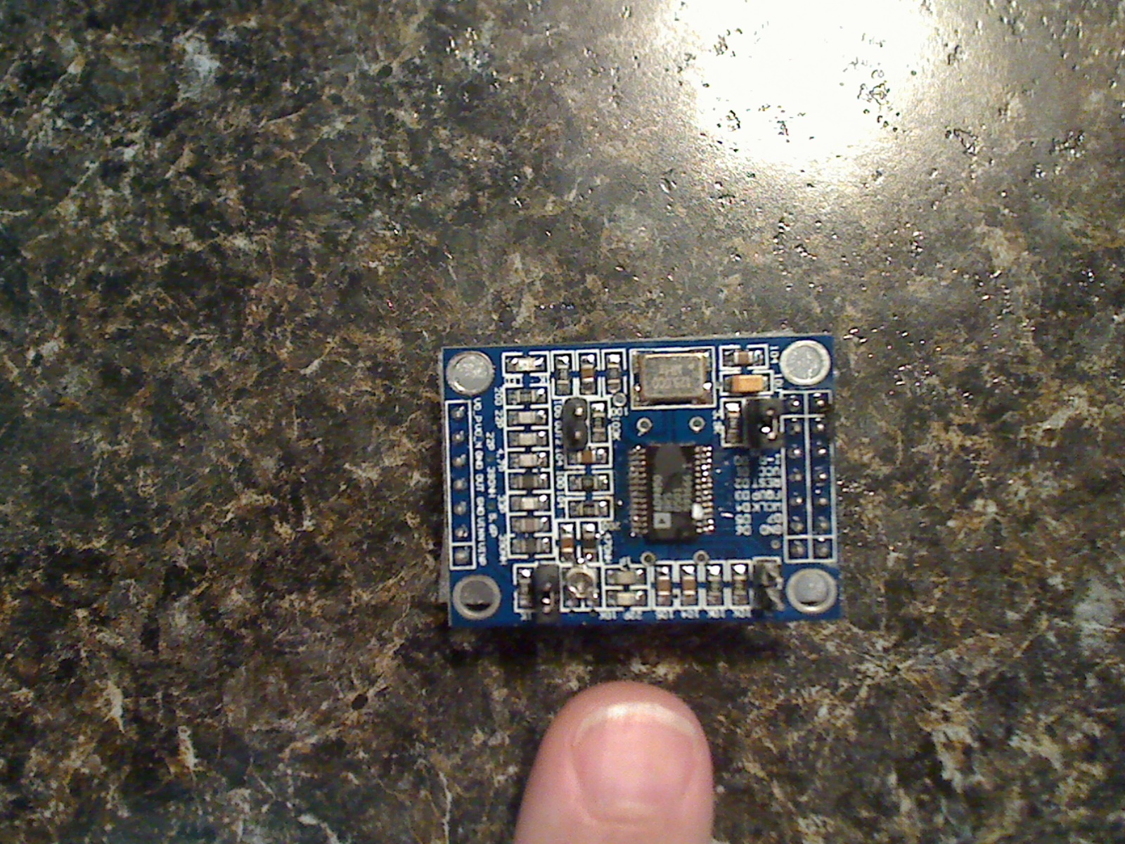
To control the AD9850 you’ll need some sort of micro-controller. Without going into too much detail you are required to send a set of serial or parallel data to the chip to set the frequency. There are numerous postings on the web detailing exactly how to do this so I won’t go into too much detail. However it has been hard to find a good AD9850 Pinout so here you go.
D0 – D7 = Parallel programming bits
GND = Ground (obvious); Vss
CLK = Serial programming clock
Latch = Serial programming latch (FQ_UD pin on 9850)
DATA = Serial programming DATA (internally tied to D7)
RST = Reset. Keep tied to GND
SQW = Square wave outputs (complementary) Duty cycle adjustable with blue pot.
SINA = Raw unfiltered AD9850 sine output
SINB = 70 MHz LPF filtered AD9850 output.
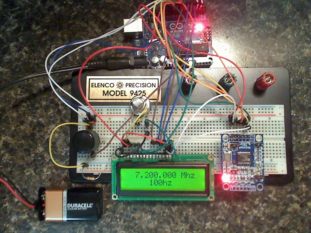
For me, the easiest way to manage the AD9850 is with an Arduino Uno. If you don’t know about the Arduino platform you should check out the official site at www.arduino.cc. I have been playing with the Arduino for only a couple of months and I already have found it to be a fantastic development platform. If you are a hobbyist tinkerer… you really can’t go wrong with one.

I have paired may AD9850 with an Arduino Uno, LCD display, Rotary encoder, and a few other small parts and have put together a very descent DDS VFO capable of any frequency between 1mhz and 30mhz (It will go to 40 if you wish). A little quick work with a protoboard and I have a nice working VFO. You can watch my video on YouTube showing how it works. I also have another video of the VFO attached to my oscilloscope.
This project is ongoing. You should be able to deduce the pin outs on all items from the Arduino Sketch but if you have questions just contact me. My schematic is a little rough as I do not tend to create them that often so let me know if you catch anything out-of-place!
Because of a lot of requests I have also created a version for IF (superhet) type receivers. The VFO now supports an Intermediate Frequency and can switch upon the HI/LOW level of one analog input on the Arduino. The IF can be anything you wish and can be additive or subtractive.
** UPDATE November, 2013 **
I have updated the sketch to write the last tuned frequency to memory and recall it upon boot-up. This is a 100% direct drop-in replacement and requires you to only upload the new sketch. The code is well documented and for those of you who modified my original sketch it should be easy enough to adapt as you see fit.
Both Arduino sketchs (IF and NON-IF), schematic, libraries, and notes are available for download here. Also, Jiri (OK1DXK) create a great drawing (aka schematic) if you wish to use an Arduino Nano. If you build something from my design please send me a picture or a video of your creation. I love to see what others do!
Or you can also send a donation via paypal to rvisokey@yahoo.com (My registered PayPal address.)
Hi, I’m wanting to build a VFO to run an old Drake 2 NT xtal controlled transmitter. I’m interested in what you have built here. I will need some kind of amp to bump up the output to 4v ptp, manual calls for 12v on 15 meter band for some reason.
Anyhow I like what you have here and let me know what you think.
Thanks, Gary KF7WNS
Gary,
You can easilly build a buffer amp to drive the signal to 4v PTP or even 12v PTP, however, I find that level somewhat huge! Typically 1v or .5v is more than ample for most circuits but if that’s what the manual for your Drake states… that’s what you’ll need.
Please remember that the output voltage of the DDS VFO varies with frequency so if you need it to output a constant level across a wide-range VFO you’ll need to design an AGC (or sorts) into your buffer to provide a constant level output. I’ve seen some great designs with simple op-amps that accomplish this with a tap into the feedback circuit. I’m not the expert here so I would recommend you get on the eham.net forums or arrl.org TIS group for more assistance.
God luck on your project.
73,
Rich
AD7C
I’ll send to your gmail account in a few moments.
Rich AD7C
I built This VFO and it works great. If you need more power try this site.
http://www.pongrance.com/dds-buffer.html
I also built this amp and it gave a 10dB boost.
Hi !!
What you need to do to rotary
work on the Arduino Mega?
Best Regards
dyzio
I am not familiar with the Arduino Mega so I can’t be of assistance. You’ll probably need to adjust the pinouts from the UNO to the MEGA as they are different. The main difference is going to be the Interrupt pins.
Sincerely,
Rich
AD7C
Hi,
I want to build this project Ad9850 plus Arduino,
but with Arduino Nano. It’s possible? It’s the same?
Thanks,
Eddi
Yes, it will work with nano. I build it. Pay attention : D10 of the Arduino goes to the DATA pin of the AD9850 and NOT D7.
You mentioned that when using a Nano, connect to data not d7 on the dds module. I see D0-D7. The schematic shows D7 on the dds to D10 on the Nano.
D7 and DATA are connected on the PCB and are the same.
This was asked a number of years ago but is still valid.
The reason the rotary does not work on the Mega2560 is due to the differences in interrupts between the Uno and the Mega2560 or or specifically the Uno’s lack of them. It turns out the fix is rather simple.
In the setup(){} function comment out the following lines and then add the two lines immediately after the commented out code like this::
/*
PCICR |= (1 << PCIE2);
PCMSK2 |= (1 << PCINT18) | (1 <=30000000){rx=rx2;}; // UPPER VFO LIMIT
if (rx =30000000){rx=rx2;}; // UPPER VFO LIMIT
if (rx <=1000000){rx=rx2;}; // LOWER VFO LIMIT
}
}
No change in pinouts necessary though I did adjust the lcd wiring with pin 4 of the lCD to D13 and pin 6 of the LCD to D12 (just swapped them) and changed:
LiquidCrystal lcd(12, 13, 7, 6, 5, 4);
TO:
LiquidCrystal lcd(13, 12, 7, 6, 5, 4);
One last thing that is not Mega2560 specific was a labeling errata in the wiring diagram. D10 of the Arduino goes to the DATA pin of the AD9850 and NOT D7. So it should read DATA and not D7 on the DDS AD9850 in the diagram. Hope this helps someone.
It works for me
Nikki
What a shame, the web code filtered out some of the code I posted. This makes the above incomplete. So I will try to describe what needs to be done instead.
On the Mega2560 use the attachInterrupt() function in the setup() part of the program. The lines that reference PCICR , PCIE2, PCMSK2, PCINT18 and PCINT19 as well as the sei(() function in setup() can be commented out or deleted. This amounts to 3 lines towards the top of the setup() function. The new code uses attachInterrupt() for INT_0 & INT_1 like this:
attachInterrupt(0,MyIsr,CHANGE)
attachInterrupt(1,MyIsr,CHANGE)
of course don’t forget the semicolons at the end of each line.
Next you simply want to change the name of the ISR service routine (called ISR) from ISR(PCINT2_vect) to void MyIsr(void). Then your’re done. I hope the web server doesn’t filter out this, If it does, then I tried.
Good luck,
Nikki
in this way?
void setup() {
lcd.begin(20,4);
lcd.backlight();
Serial.begin(9600);
lcd.setCursor(0,0); // Se pone el cursor en la primera posición de la pantalla
pinMode(A0,INPUT); // Connect to a button that goes to GND on push
digitalWrite(A0,HIGH);
//PCICR |= (1 << PCIE2);
//PCMSK2 |= (1 << PCINT18) | (1 <=30000000){rx=rx2;}; // UPPER VFO LIMIT
if (rx <=1000000){rx=rx2;}; // LOWER VFO LIMIT
}
}
well i have a problem :
dds9850.ino: In function 'void setup()':
dds9850.ino:33:20: error: 'MyIsr' was not declared in this scope
dds9850.ino: At global scope:
dds9850.ino:46:6: error: expected constructor, destructor, or type conversion before '(' token
Error de compilación
//PCICR |= (1 << PCIE2);
//PCMSK2 |= (1 << PCINT18) | (1 <=30000000){rx=rx2;}; // UPPER VFO LIMIT
if (rx <=1000000){rx=rx2;}; // LOWER VFO LIMIT
}
}
good morning i’m trying to load the code into an atmega1284p and i have a problem with the rotary encorder can you help me?
in terms of the changes I need to make
Post your problem. However, most times you can fix the rotary encoded by making sure you use the proper case: Rotary not rotary.
good morning I am loading the file on arduino nano, uno, mega it works perfectly !!!! I also uploaded it to atmega 1284 and I see that it wants a different library for the rotary encoder, this is the only problem, can someone help me? I am new to programming !!! Thanks in advance.
the issue was resolved was simple
Thanks Nikki…I revisited this project and was able to get the encoder working on an old Mega Arduino.
Thanks Brent W1IA
Hi, I too am planning on building this circuit. I was wondering if you’ve messed around with the AD9850 Library for the Arduino? I appears to have simplified things quite a bit. I’m also looking for other examples using the AD9850. I bought 2 for pocket change. Here’s the library:
http://code.google.com/p/ad9850-arduino/
Never used the library as I had no issue controlling it for what I needed it to do but thanks for the tip! 73, AD7C – Rich.
Hello! Could you give me the both type of AD9850 and rotary encoder . Thank you : )
Analog Devices AD9850. Get on ebay.
The rotary encoder I used was from a junk drawer, however, you can find a similar one for $3-$4USD at sparkfun.com or mouser.com.
Just picked up the rotary encoders on ebay for about a buck each.
Wayne.
Might this be a cheap replacement for a bad PTO on a TenTec Century 21 I have? Thoughts? Thanks for your work!
Ronny
K4RJJ
I don’t know much about Permeability Tuned Oscillator circuits, however, I see no reason why you can’t use it. Realize that it would replace the entire PTO section (or rather VFO). The nice part is that if you did replace it with the AD9850 you would get a much wider tuning range over the PTO. 73 – AD7C
For the Century 21, Ten-Tec radios and the Drake TR-7, you might want to check out this website to see about a dual digital DDS VFO using the AD-9850. All the code is even published there:
http://www.k3jls.net
Rich,
Please send me the new code for superhet receivers. I have a SW receiver that I built with the NE602 that uses 455khz and it would be awesome to have that figured in. Thanks for commenting a lot in the code. It helps for those of us that are struggling. This is really great that your doing this. Having a powerful VFO like this is
worth big bucks!
Harold Lacadie
Me Again,
Well I built the circuit EXACTLY as you have described using inexpensive EBAY parts it and your software. Oh my sweet Lord! This is the coolest thing ever. Tomorrow night, it gets a real workout on my little superhet. Your setup is flawless!
Glad it works well for you. FYI: The NE602 doesn’t require much drive (input) to work, however, you may find that some designs require a little extra “oomph” from the AD9850 output. KF0XO has a simple buffer circuit a few posts back that boosts the output around 10db.
Love to see a photo of it in action!
73, Rich AD7C
Rich,
I connected the Arduino VFO up to my little NE602 superhet last night. found out 2 things:
1). A coupling cap is required (there must be some DC in the sine wave or something.
2). The NE602 needed the entire waveform to work well and seemed to want more; need to make a buffer.
Other than that, the tuning was smooth and clear. I even tuned down to the upper AM bradcast band. Found some spanish broadcast ot the Redsox game. I’m going to alter the code to go lower into the broacast band, make a buffer and maybe stick a little MMIC before the first IF can. Fun stuff dude! Video coming soon I hope.
If you watch my 2nd video of the AD9850 on Youtube you can see that the lower in Hertz you go… the more powerful the sine wave output. So in the AM band you may be able to work without a buffer but, most likely, anything above 7mhz will require one.
Fantastic circuit worked straight away with the same components. I am very much interested in the new version could you please email at glitsun@hotmail.co.uk
Many Thanks a lot for the wonderful circuit.
Regards
Glit.
M0HPF
Hello
I want to ask you about the schematic I try the connection thet you made but it doesn’t work can you help me please
May people have built this circuit without issue. Please double check all your wiring.
I built the circuit, but the software wouldn’t compile properly. I ended up putting the code for rotary.h into the beginning of the main program and removing the “#include rotary.h” line. The rotary encoder wouldn’t work to change frequency. I figured out that adding external 10k pullup resistors to the two encoder outputs fixed the problem, and now it works fine. I’m happy. I’m not sure what “# include Arduino.h” refers to. I hope this can help someone.
I did the same, Luke. It worked great for me.
Rich, thanks for helping us all!!
Stan
aj4sn
Rich,
Sorry to be a PIA but my programming skills are pretty bad when it comes to the Arduino (C language). Could you please send me the new version of your software that takes into account the IF frequency you mention above for June 6th?
In looking at the AD9850 board’s specifications there is a jumper for serial mode – yet in most of the pictures I don’t see this jumper used. Is this jumper necessary or not?
Thanks
The jumper let’s you select between parallel or serial input, however, you can also software select it. Generally unnecessary.
Rich
AD7C
Nice Info, look forward to try this !
Pingback: 7MHZ VFO with Arduino and AD9850 | AD7C
Hi Richard,
For past few days I was trying to assemble the AD9850+LCD+rotary Encoder for the HF VFO. I have almost made it but for the rotary encoder part. In the sketch you have published I am getting some errors especially for the rotary encoder code lines .First in line no 11- it says ‘Rotary’ does not name a type, Then in line no 40 – ‘r’ was not declared in this scope .Next in line no 42 – ‘DIR_CW’ was not declared in this scope .I am not able to address these 3 errors. Hope you can help me.Thanks in advance for your time.
73
(Pravinkumar Anandan)
AB9XC
ab9xc@yahoo.com
You most likely did not include the rotary encoder libraries. You have to include the extra libraries for my sketch to work. While I have provided the libraries in the ZIP file, you have to setup them up to be correctly imported during build/compile. See: http://arduino.cc/en/Guide/Libraries
AD7C
Rich
Hi Rich,
I tried to instal the rotary encoder libraries as instructed by you. But it says already there is a library called
” Encoder” and true to it the rotary encoder works in stand alone mode. But somehow when I try to include it is not taking saying it is not named a type. In your experience of Arduino what may be the reason it is taking “Encoder” but not taking “Rotary” ? Thanks for your time.
73
(Pravin)
AB9XC
Sorry. Don’t know how much more help I can be. I have never experienced the problem you describe. You may want to remove then re-install everything related to the project (Arduino environment and all). Make sure you have the latest version of the Arduino environment when you re-install. Lot’s have people have downloaded my code and it has worked without issue. You can also try posting to the Arudino forums to see if someone there can help as well.
Rich
AD7C
I have tried that also but the problem persists . Anyway thanks for all your help and if and when I solve this problem I will certainly update you.
73
(Pravinkumar Anandan)
AB9XC
Hi, I finally got hold of all the parts needed for the arduino ad9850 vfo project. My question is I guess the lcd I bought is the lcd keypad shield. Will this work? I’m new to this arduino and I tried to upload the code and there seems to be an error every time I do it. Could you please help me with these? 73′s and more power.
The code was designed for an external Hitachi styled LCD unit and not the Arduino LCD shield. However, you it can be made to work with the shield. You will need to look at the shield pin-outs (RS, write, Data, etc) and match those to the data pin-outs I used in my schematic. You’ll then need to change the code in my sketch to assign the correct pins. It’s fully documented so you can easily find the pin assignments are re-arrange them. It’s going to be a lot of work if the new pin-outs use pins assigned to the rotary encoder or DDS unit.
Sorry! I don’t have a LCD shield so I can’t help you much with this one unless you feel like sending me one to proto . My $.02. Get a basic, plain, simple LCD. The’re $5-$8. Ebay is your friend.
Rich
AD7C
Hi Richard,
With the active help of some Arduino forum members I was able to successfully instal the “Rotary” library into my Arduino IDE and now able to compile the AD9850 DDS code . Just now I loaded it into a ATMega328 chip and it has started to work as per your design. I am wondering whether we can modify it such that it can be used as a swept frequency source for an antenna analyzer application .
Thanks a lot for your wonderful yet simple circuit and code.
73
(Pravinkumar Anandan)
AB9XC
Thank you so very much for the FW and the schematics.
Hello Rich,
My children’s Aurduino board was sitting idle after they played around building a few basic projects during their last summer holidays….
The simplicity of the Aurdino attracted me, and while Googling for more info I came across your web page. I’m glad I did !
Your code worked the very first time I switched it on, and your well commented sketch helped me a great deal in my intro to the Uno.
Please watch my video @ http://www.youtube.com/watch?v=LiPcl01YB9o
This is an ongoing project for a HF to 2m transverter.
73
Hello Rich: I have a question reguarding downloading the rotary libraries. There are 2 rotary libraries, rotary3 and rotary. Do I need to add both to the IDE? Or am I looking at the wrong file?
73
Dave
Dave… those files are part of the original source code. As I did not write that code but rather just modify it I felt it necessary to include and credit the original authors. Ignore everything in the RotarySource folder unless you want to make source code changes (doubt it).
You are only interested in importing the 2 files in \libraries\rotary folder: rotary.cpp and rotary.h and my main arduiono sketch (.ino file). As there has been some confusion please only 1 of the .ino files. More is explained in the ReadMe.txt file.
73, Rich AD7C
Hi Rich: Thank’s for the help. I am new to Andurino so just needed a step in the right direction. All is OK now once I downloaded the coerrect file
73
Dave
Wb4CHK
Hi Rich,
I will be very grateful if can you tell me how to change the code such that it can be used as a swept frequency antenna analyzer with appropriate LPF from a bank of Low Pass Filters etc. Thanks in advance for your time.
73
DE
AB9XC
(Pravin)
Hi Rich. I am designing a board that will plug into the Arduino and have the 9850 DDS module plug into the top of the board. From your schematic you have the data line from D7 on the 9850 module going to the pin10 on the Arduino.(UNO) which you assigned as Data 10. It would make a cleaner board if I connected Data 10 on the Arduino directly to Data in on the 9850 board.They seem to be connected. Any problem connecting Data 10 directly to Data in on the 9850 module rather than D7? I hope this makes sense!!!
73
Dave WB4CHK
I sent you a personal email with my contact info. Let’s discuss there.
how to generate the Arduino Uno with two sinusoids using two plates DDS9850 and only one arduino can someone help me
Marcos,
Doing what you ask would be difficult. The Arduino UNO has just enough outputs to run one AD9850. You probably would need to run an Ardunino Mega to use two boards. Sorry… I’ll be unable to help you with your project.
Rich
AD7C
Great project made up one for myself!
I did a blog post on it as well.
http://tobyrobb.com/wordpress/?p=577
Toby Robb.
Vk2TOB
Hi Rich,
I tried the sketch to my board, it works well, but the dial speed when change the frequency is too slow for me, i just using generic and commons 3 pins rotary encoder (ticking when i spin it type). i tried to lowering and increasing delay speed with change the value from 250 to 100 and lower with mean i need it that the rotary encoder will response quicker, but i don’t feel many changes, anyone have ideas to fix my problem?
Thank’s Rich, this sketch is simple and easy, hope i can adding some menus in future
Rudik,
Did you also hook up the push-button “switch” as shown on the schematic? When you push the switch it changes the rate (speed) at which the rotary encoder advances/declines the frequency. YOU DO NOT need to modify the sketch code to get the rotary encoder to respond faster. I am also using a generic 3 pin encoder.
Rich
AD7C
Hi Rich,
Well, because i don’t have the rotary encoder with 5 pins, i just used 3 pins rotary encoder type, and change the push button with ordinary push button switch, in my understanding, it’s should be no problem.
Another important function i wondering is auto saved last frequency used, so in case we turning the controller off, the last dial should still remain in previous setting. I am and my friend is working with this, so, i will updating the updated sketch here for everyone use.
thank you
rudik
Hi Rich,
I built your DDS project, it works great. Just wondering what the switch does that is connected to A5 on the Arduino? I have mine hooked up as the schematic shows but it doesn’t appear to do anything. Thanks.
Joel
KB6QVI
The switch changes the steps (rate) of tuning. 10hz, 100hz, 1khz, etc. If your switch does nothing check the connections. Most rotary encoders have a ‘switch’ built in that actuate when you depress them so an external switch is not necessary. However, you can use an external switch as you did. Watch the video of this build on my YouTube page and you can see the action of the switch.
Rich
AD7C
Using Arduino Nano board & eBay AD9850 board.
Using with old Motorola Micom HF SSB radio covers 1.8 to 18Mhz
A very nice little sketch and project for the Arduino. Thank you
Somebody mentioned the switch on A5 and that’s the effectively the TX/RX of if shift state switch as it changes the output frequency to be the one shown on the display, less the constant defined by ‘iffreq’.
It is not the one to change the DDS switching steps which is on A0 and is the push button on the rotary encoder.
It certainly works very well and at present I have mine working with the other DDS available on Ebay which has slightly different pin outs and names.
This may help others to use the different DDS boards out there and the pin markings on the different boards are compared here:
D7 = DATA
MCLK = W_CLK
FQUP = FU_UO
RST = RESET
I also changed the line: lcd.print (” “);
to be
lcd.print (“rx”)
simply to show that it’s in if shift more .
Brilliant and thanks again
Dale G4IPZ
anyone have updates regarding the the problem with the last used frequency dialed when system goes shutdown? i mean, when last time i tuned to 7.100.000 Hz, then i turned off the system, i want the dial frequency remain at 7.100.000, Hz, not to the default value as i stated in sketch. i think this should become the basic function anyway.
That is not a problem that is by design. There is no routine to store the last entered (dialed) frequency in the DDS so when power is removed and restored the system always resets back to the default VFO frequency.
However, I am working on this as an improvement… with some other items. Anyone wishing notice when I am done can send an email to AD7C @ ARRL.NET and I will add them to the notify list.
Pingback: Nachbau eines digitalen Sinusgenerators « Peter Hostermann
Rich,
Great project, I have built it around the Uno, the Nano, and the Pro Mini and they all work perfectly. I prefer the Pro Mini as they are dirt cheap. The only thing that would make this better would be if it had the ability to remember the last frequency you were on and you are working on that, thanks. BTW, mine draws 140ma with the Pro Mini module.
Joel KB6QVI
This little project has really sucked me in HI !
My versions have been run on a UNO, a NANO and even on a UNO bootloader chip programmed and built stand-alone on veroboard.
It’s been a great learning curve.
So far I’ve rewritten quite a bit of the sketch so it now uses an 8 x 2 display, has separate up/down buttons for the step values, has an IF shift inhibit switch depending on what I’m driving with it and the ability to change the shift frequency by a push button. I’m now working on saving the chosen shift into the EEPROM and learning masses as I go along.
One of my next mods will be to use an I2C display to release the digital pins for other uses.
Fantastic fun!
Excellent! Nice to know people are taking my base and expanding it.
Completed build on the WB4CHK pcb and barring a few toubleshoots we are up and working with a Sine Wave to be proud of.
Minor problems if they help anyone.
Keep the IF and the non-IF sketches in separate folders when you load one of them into the arduino IDE you get duplicate declarations etc.
Others : my faults..
Using ribbon cable – one faulty data connection traced with ohmeter an fixed.
22K might be bit to large for the contrast – it is all in the last smidgin of the turn of the pot. (Plans say 25K – but 22k on hand here)
Non critical.
Wired the 12V supply into the 5V regulator using connector from the aruduino.
All works OK but tabbed-regulator gets a bit warm. Fix this next time with 9V into arduino from the 78L09. (with 12v into the 09).
The project is to become my new bench RF sig generator so will be looking at the N3ZI buffer amp and a stepped attenuator. Possible calibration later or some kind of const voltage amp.
Enjoy the project everyone!
73
Toni
G6XMO
Moving the IF version out of the folder containing both .ino files, solved duplicate declaration error for me too! Compiler was finding first error at ‘void storeMEM()’ Using Linux Mint 17.1 and Arduino 1:1.05. Thanks Tony for the comment. Thanks to Rich for the wonderful project!
Bob KD0JIY
Just finished installing Arduino Ver. 1.6.5 on Xp. Downloaded and tried compiling non IF version of vfo. Got the duplicate declaration error, when both .ino files were in the same folder.
Removed the IF version and then the remaining one compiled fine! The XP operating system is a virtual one using Oracle virtual box on Linux Mint 17.1 . I found out about the AD9850 Arduino shield (by WB4CHK) at Rich’s site about an hour ago. Neat!
Tnx agn to Rich, Tony, and WB4CHK
Bob KD0JIY
Installed Arduino Ver. 1.6.5 on Windows 7 Pro Sp1 with all Microsoft updates. Compiled (arduino ‘verify’) Rich’s non-IF .ino file. Got the error ‘duplicate Rotary r’. Removing the IF .ino file from its original folder solved the problem. The non-IF file compiled 100%.
This time the Windows 7 operating system was on a normal hard drive, not virtual. I need to get some parts, and try this vfo. Thanks again, to Rich and contributors!
Bob KD0JIY
Pingback: DSS VFO Update – Last Frequency Saved in EEPROM | AD7C
** Code Update **
Version 2.0 of both sketches is release. Version 2.0 saves the last dialed frequency to EEPROM memory and reloads it at boot-up. Code is 100% direct replacement of old code.
If there are any questions please just ask.
73,
Rich
AD7C
Would it be possible to control 2 DDS modules to allow I-Q outputs for SDR applications.
maybe use extra arduino output pin to select DDS module, send same freq data 32 bits, need control word to for each DDS module for 0′ & 90′ phases.
Frank. Very possible to drive 2 AD9850 boards. However, I would probably want to use an Arduino Mega as they have more digital and analog pins easily allowing for the extra AD9850. While I am no expert on SDR and IQ I see a problem as I am not sure how you would control the phase of the AD9850′s. Something conquerable in code perhaps but a little beyond me at this point.
73,
RICH
AD7C
Hi Rich,
Feed both DDS modules with 1 clock source with equal wire length.
AD9850 control byte can select phase value (5 bits)
thinking to use Arduino I/O pins 0-1 to select chip when loading 40 bits data into DDS chip.
Hi, very much appreciate your design.
I downloaded the non-IF version 2.0.
I am having a problem compiling the code.
Probably my problem.
For statement Rotary r = Rotary(2,3),
I get error ‘Rotary’ does not name a type
Help
You didn’t load the rotary encoder library that was included in the zip file. Load the library.
Rich
AD7C
Have been looking around at how to incorporate some wobbulator functionality into the DDS VFO so that it becomes a great bench tool – RF signal generator and filter tester/alignment in one.
Using the existing two switches and adding an I2C DAC to make the sweep voltage it should be possible to program into the existing setup a menu for VFO and another menu for Wob. The IF switch would make an Escape button and the rotary encoder an Enter keep. The Wob sweep limits could be set with the rotary encoder and the step too.
I have a o-scope that will take X-Y inputs; the idea is that the filter under test gets the sweeping frequency (with the sweep voltage from the DAC) and the output of the filter is then displayed on the o-scope Y. The set frequency and DAC voltage are set on the same loop in software.
The I2C DAC proposed is the MCP4725. These are an inexpensive chip. The cost of postage is actually more than the IC. You can get a breakout board from Adafruit or Sparkfun. Even using a local distributor in the UK the shipping cost doubles the cost of the purchase. So I’ve decided to get the chip and homebrew the circuit. Will probably add it ‘island style’ on the Arduino DDS VFO “Shield”.
73
Tony
Please,
keep us posted on this project!
Update on the wobbulator project.
I have now got a MCP4725 working with the arduino on its own and drawing an nice sine wave on the scope. This was the first time I have worked with the SOT23-6 package. So much so that you open the packet from your supplier and say ‘where is the IC’. The are really tiny for something so useful. What a mess though – I switched the SDA and SCL pins so the thing wouldn’t work at first. When I wired them correctly the chip registered on the I2C probe software and bingo – here we are!
I bought the ‘raw’ chips rather than the breakout board from Sparkfun or Adafruit. Nothing against these people they are great. However, my local supplier didn’t keep the breakout board and I priced up the board at UKPounds 12 delivered, when the chips are UKPence 80p each. Made some adaptor pads using press and peel (really must buy some new stock of this).
Next job now we have a DDS VFO and a DAC is to integrate the two software modules into a menu driven VFO/Wobbulator.
More next week.
Bit of a haitus in the project – I have completed the hardware element and though it was time to box it up (with a little wriggle room for mods) before finalising the software.
I did get the DAC to sweep across the X trace of the scope and the VFO to sweep +/- 2KHz of a centre frequency.
Idea of boxing it up it to 1) try the RF shielding and see if anymore bypass or filtering is needed and 2) to get the project out of the ‘loads of wires’ phase and safe from short circuits on the bench.
The plan is to allow the boxed project to be programmed by having the USB connector accessible.
A thought – for an antenna analyser – use some of the design from the 4SQRP projected ‘tenna dipper’ should be able to adapt this on ‘manhattan’ construction.
Hi Rich,
Hope you still remember me . I have succssfully assembelled your AD9850 DDS VFO design using Arduino ATMEGA328 chip a few months back. Thanks to you it is working fine and of great use to me as a general purpose VFO. Now I want to put similar VFO s for more specialised uses like (1) Antenna Analyser (2) SDR etc. I have got a few AD9850 boards and an AD9851 board through ebay.
Regarding (1) Antenna Analyer I have alreday requested you to kindly publish the code, hope you are on the job time permits.
(2) For SDR it will be awsome if two similar 9850 boards can controlled by a single Arduino (I think ATMEGA328 will be sucfficient) as it requires just an extra pin (to drive two separate W_Clks with 90 degree phase delay) than the single board . If it is difficult to do in software I think we can do it in hardware without the need of the extra pin if the clock frequency is known. We can have a full HF SDR without the need to use X4 VFO and the 7474 chips . I request your opinion about the same.
I am in the process of upgrading the AD9850 software to include the “last frequency” feature you published recently. So far not succssful on it and will let you know the result shortly.
Regarding the AD9851 board I will be very grateful if you can publish the code for a HF+VHF VFO with LCD & encoder in one of your future blogs. Hope I am not demanding too much from you.
73
DE AB9XC
(Pravin)
Pravin,
I do not have time, at present, to work on the antenna analyzer. Work and other projects have kept me away from exploring the code. However, I do plan on someday generating a code an schematic but I can not state a time-frame.
For the SDR I suggest you seek out another user who posted some items about SDR on this board. Frank VK3ZFS has shown an interest in the same topic and together you both may be able to find a way to use dual AD9850′s to build an SDR.
I would suggest to you that you take a look at http://arduino.cc/en/Reference/HomePage. With the current code I have published an a little exploring you can build all the items you requested without my help. The arduino platform is simple and learning is part of the fun. Many people have taken my DDS project and expanded on it by learning how to program the arduino.
To get the AD9851 working in my sketch you should only need to replace one line. Replace my line with this new line: int32_t freq = frequency * 4294967296.0 / 180.0e6;
73,
Rich
Hi Rich,
Thanks for your suggestions and I will try to learn some code programming. Will certainly keep you posted about the modifications/projects if and when I make it. Hope it will be useful to many other hams also through this board.
73
DE AB9XC
(Pravin)
Hi Frank,
I would like to know how far you succeded in the quadrature VFO design using two AD9850 boards controlled by single Arduino? Any idea what is the W_CLK frequency ?
73
DE AB9XC
(Pravin)
Did any one get the two in quadrature? Maybe just use the two outputs and a delay line? Most software will correct for this I’m reading. SDR# ha that function.
Rich,
I run the new compile the new version of your software and I get a “Rotary redefinition error..
The newer Rotary library is loaded.
Windows and Linux
I compile the old version and it’s fine.
Odd problem. I’ve experienced this as well. Make sure you open the file in Arduino Program and then you must save the file, typically in the /mydocuments/Arduino folder (varies by OS). If you don’t save the file before you compile… that error will appear. Also make sure you have the latest version of the Arduino program.
Rich
I got the same thing — its because the AD9850_LCD_ROTARY_WMENUS and AD9850_LCD_ROTARY_WMENUS_IF are both opening when they’re in the same directory. Move one or the other up a level and it compiles just fine.
compile error “redefinition of ‘Rotary r’ ”
Arduino 1.6.7
Hi Rich,
I successfully tried your project using Arduino Nano v.3.0. Almost no changes. It works very nice. Thank you very much.
73′s
Jiri (OK1DXK)
All is OK, but “verifying” stoped here “Rotary r = Rotary(2,3)….” ?
Antero, Make sure you have newest version of Arduino software. You MUST save the new sketch with a valid name and correctly have the libraries imported.
73,
Rich
AD7C
Copy the text from the sketch and paste into a new MS WORD doc. Then copy out of the word doc and paste back into a NEW sketch. There is something that happens to the formatting that WORD fixes automatically (probably line breaks).
Make sure the libraries are there as others recommended.
Also here are some links to info on syncing two of these badboys in Quadrature for the SDR IQ system.
http://www.analog.com/static/imported-files/application_notes/599711852800924681833359689AN-587.pdf
http://blog.2gn.com/electronics/sync-two-ad9850-dds-modules-from-the-same-clock/
hi great circuit- i built it and works good. i plan on making a small radio. have 1 question- i used a small ebay arduino mini /nano and it dosn’t have a pin a5 for the mf switch so i hooked it up to a3(it only has a0 thru a3). could you tell me were in the program to change a5 to a3? not good at programming yet but having fun learning.
thanks
steve
pinMode(A5,INPUT); // IF sense **********
Change to A3.
Rich
AD7C
Hi Steve.
Some of the bootleg Arduino Mini’s ‘hide’ the A4 to A7 pins in odd places on the board and often not too clearly screen printed.
The ones I use have a separate block of holes which are beneath the ICSP connector.
The bootleg Arduino Nano’s I use have the A4 to A7 in the normal place on one side folowing on from, A0 to A3.
It is worth noting that some Chinese copies advertised as Nanos are in fact Pro Minis. I’m pretty sure that the easiest way to tell one from the other is that if it has a usb connector it’s a Nano if it doesn’t then it’s a Mini.
Also check that the ones you buy are using the 328 device as some of the older ones are still floating about out there.
Slim G4IPZ
Update 15/12/2013
Incrementally nearer to the final product.
I’ve got a crude break out of the loops that end the various functions and return to the main menu.
When A1 goes low the loop should end.
This works but is a bit hit and miss….
do{
buttonstate2 = digitalRead(A1);
}while (buttonstate2 == HIGH);
(moved my button2 onto A1 for some reason or other early in the project.)
I realise that you have be ‘caught’ pressing the button with this method.
Anyone have a better idea?
Project nearly finished – if anyone can help with this one…
I have put in a rudimentary menu system that allows selection of Sig Gen or Wobbulator.
Problem is – if you break out of the wobbulator do while loop using the button the button press becomes the select button for the menu system which selects the first option – which is sig gen.
Anyone know how to stop this from happening?
This is acting as an escape button…
do{
buttonstate2 = digitalRead(A1);
}while (buttonstate2 == HIGH);
the button above is the select button as well as escape, so the keypress is caught and selects the first option on the main menu instead of stopping at the main menu.
Your help appreciated then I can pass on the project to the group here if they want to give it a try.
I’m thinking of adding a new button for “escape” to break the loops but would prefer not to as the unit is cased up and I’d have to dismantle etc to drill a new hole for another button.
Hi Rich,
I have been using your original sketch for a while now with no problems but when I uploaded the new Rev 2.0 sketch it still doesn’t remember the last frequency. I’ve started from scratch several times with the same results. Have you any ideas what i’m doing wrong, it works perfect just won’t remember.
I am guessing you didn’t see this section in the Sketch… Just change to 0.
int ForceFreq = 1; // Change this to 0 after you upload and run a working sketch to activate the EEPROM memory. YOU MUST PUT THIS TO 0 AND UPLOAD THE SKETCH AGAIN AFTER STARTING FREQUENCY IS SET!
73,
Rich
You’re right Rich, I didn’t see that in the sketch. I will make the changes, thanks.
Joel
KB6QVI
Hi Rich,
I have built a multiband BITx Txvr designed by G6LBQ The IF is 10.7 MHz
I am also in the process of making your DDS vfo, Thankyou for publishing your design) I managed to get the IF offset to work. but is it possible to have it change from addative to subtractive or vice versa when the frequency changes to, say above 10 MHz. Excelent project Thanks……………Peter (GW4ZUA)
Peter,
The code is already setup to do what you request. Read the instructions.
Rich
AD7C
Rich
I just wanted to say thank you for a wonderful website. I just assembled a prototype of the DDS VFO and it works like a champ. I plan to use it with a small amp to make a VFO to replace xtals used in the older transmitters. I am using the IF version so I can offset the sig gen during receive. I haven’t used it yet but I see no reason why it won’t work. Thanks again.
I modified the code a bit to remove some of the tuning step choices, it was easy to do even for a non coder such as myself.
Larry Naumann
n0sa
Glad it worked Larry!
73,
Rich
AD7C
Great little project, and valuable learning tool. I didn’t get mine to work first time up, but read over the posts and found my problem, for some reason the rotary folder did not have some files when imported. Fixed problem, and now to box it. I just want to say thanks for making the code and help you gave in this project.
John N8RVE
Hello great work, and thanks for sharing. I am new to arduino and am still playing around with the starter projects. I am wotking on getting this dds working. Once I do i was wondering if there was a way to send an adjustable reset to the dds with another encoder to do burst pulses. Would like to be able to control the total pulse count and space between pulses. I have been trying to figure it out but am so lost. thanks
Thanks for the great code, I had to make a few minor mods for the AD9851
Gary VK8BN
In my version I have changed the 100 ohm resistor as follows: +5 VCC –10 k–A0—encoder. So I have cured the instability of the encoder. Thanks to YO6OGW for the right advice.
Hi Rich,
Thank you, I’ve been made the second version by your updated sketch. first try i confusing because the random frequency at 143.XXX.XXX Hz appeared on LCD display, so i read your sketch comments in program line about what we must do double uploading by 1 and 0 changes in sketch. now the DDS is working as I expected, when the system off and on again, the frequency setting still remain on last position.
I changed the default frequency setting to 3 MHz because right now i do some 80 meter band experiments, and use this DDS VFO with Arduino Control as the frequency generator.
thank you,
After hitting some bumps (I’m new at Arduino) I have the circuit working on the breadboard. I have a nice waveform of 1V PP, open circuit and 0.5V PP across a 47 Ohm resistor. I can hear a nice strong signal in a receiver across the room. I can see this as a problem when trying to receive signals. I found that the Arduino and/or the AD9850 are too slow to recover from keying the power. I need a way to turn the VFO on while transmitting and off while receiving. Or, shift the frequency out of the receiver band-pass during receive. The 2NT transmitter I want to use has a VFO keying relay that goes to ground during transmit. Anyone have an idea?
The OK1DXK drawing has a push button bringing pen A5 to ground through a 1k resistor. This is labeled MF Frequency Shift; I can’t see that this does anything. Maybe this is for the IF version of the Sketch?
Regards,
Stew ke4yh
I’m a little confused? Don’t you use the same DDS for your TX and RX. Are you using a different oscillator during TX/RX? You mentioned you’re worried about RX then say you want to turn if off for TX. I don’t know why you want to turn it off when transmitting. You may want to explain better so the forum can best answer your question.
RE: A5
Putting A5 to ground shifts the frequency, at least in my version of the code. The amount of shift is determined by a setting set in the top portion of the code (easily found).
Rich
AD7C
Hi Rich,
I will be using separate RX and TX. Old Drake 2NT TX and R4B RX. If the VFO is running during receive it blocks incoming signals. Right now I’m using the non-IF sketch and perhaps I should be using the IF version so I can off-set the VFO during receive. Is that possible?
Thanks,
Stew ke4yh
Yes. If you use the IF version you can then utilize the offset to move the frequency anywhere you wish during the receive.
Rich
AD7C
Hi,
I have seen many people use AD7C developed Arduinoi Code with an AD9850 DDS VFO as a LO for HF receivers . But wondering how is the performance of the RX with respect to the sensitivity and spurious rejection especially around the Xtal osillating frequency of 16MHz !! Can anybody enlighten me what happens when we tune to near 16MHz region ? Thanks a lot for Rich for his wonderful code and prompt clarification of doubts.
(AB9XC)
Pravin
Hello,
a few weaks ago i found a new Arduino shield. Beside LCD it also is including an increment encoder and some joystick control:
( http://www.elecfreaks.com/wiki/index.php?title=LCD_Key_Shield )
So my idea was, when using it in conjunction with the chinese DDS module and the UNO, this must be the ideal hardware for the DDS generator project.
Here you can see my results:
http://www.kh-gps.de/dds_ad7c_dj7oo.gif
http://www.kh-gps.de/dds_ad7c_dj7oo.ino
What else is planned, is also storing the step spacings.
73 de Klaus, DJ7OO
Hi Rich, great project. Thank you for making this available. My VFO is almost complete. Waiting for parts for the LT1253 buffer amp. I am restoring on old tube Johnson Messenger CB transceiver and converting it to 29 Mhz AM. Crystals are high $$$ now days so this is perfect for a crystal substitute. Having the IF offset will be great as the Johnson wants the receive crystals to be 455 Khz lower than the operating frequency. I will use a relay in the transceivers PTT circuit to operate the A5 switching.
 73, Randy, W5KCM
One thing I was wondering, if anyone has found a good way to CW Key the output? Possibly, this could be added into the Arduino Sketch code or the AD9850 output could be keyed? With some buffer amp and filtering these VFO’s would make nice QRP transmitters. Just need to have a way to plug in a key.
Well, finally finished my DDS VFO, AD9850 Chinese module Arduino mini. The AD9850 and oscillator module ran very hot on 5 volts. Runs much cooler on 3.3 volts. Used the mod by putting 2 diodes in series with the 5 v supply. Drops the voltage to about 3.4 volts. Built the LM1253 buffer amp and this gives good clean consistent output up to 30 Mhz. Works great.
Looking for a couple items,
1. A way to CW key the output ?
2. A good way to adjust the output level with a pot?
73, Randy, w5kcm
Here is a link to photos of my finished DDS VFO Project.
https://www.flickr.com/photos/wb5kcm/sets/72157645003013556
73, Randy, w5kcm
Hi there Rich. Firstly, thanks for a great and well documented project.
I am new to Arduino, but I have found it a lot less daunting
than some other more complex DDS sketches.
I have changed the code around a little, and added a signal meter, using the lcdbargraph library.
The past few weeks have been a great learning curve and I,m very pleased with the results.
I would now like to take this further and add some memory options,but I seem to have hit a brick wall!
Does anyone have any ideas as a starting point?
Thanks & 73′s John G8FPN
Hi
Any one have any ideas please, i cant seem to get the rotary encoder to work, the push button part of it works fine but thats all
Any ideas please
Cheers
SORTED FOLKS
Turned out to be that the brand new Rotary encoder i brought had 2 of its pins shorted out with a lump of solder, removed the solder and it now works fine, Many thanks for the design
I’m really impressed with your writing skills
as well as with the layout on your blog. Is this a paid theme or did you modify it yourself?
Anyway keep up the nice quality writing, it’s rare to see a nice blog
like this one these days.
Hi, I have built the VFO exactly as the schematic and double checked wiring, but I am getting a very strange problem. The square and sine waves are not the same frequency as the LED display. Have the same effect on three 9850 modules? when the LCD reads 10.Mhz I get 5.8080 Mhz. At 6.0Mhz on the LCD I am getting 1.80900 Mhz.. At 4.0Mhz I am getting 191.Khz. I have not altered the sketch at all. Any ideas before I pull out more grey hairs, please
I would suspect you are using the IF version of the code and the difference in display vs. output frequency is because of the IF offset of 4.192mhz. Did you read my code “readme” file? The IF offset is clearly explained. Just turn it off or use the NON-IF version of the code.
Rich
AD7C
I never post comment like this otherwise but i feel i have to complement you for your great work. I have had an AD9850 for a while but i have never come around to doing anything with it until reading this post and the material you have put out for download. Thank you very much! Iĺl throw in a small donation too. Thanks again.
Glad you like it!
Rich
AD7C
Hi,
Can we use arduino + AD9850 for an all band VFO lets say in place of a DDS VFOs made using PICs ?? Costruction of the once in you post seems to be a very simple compared to the ones with PICs. I believe only the programming needs to be worked upon for an all band VFO. What are your thoughts around this idea ??
Amogh J
Yes. The Arduino + AD9850 is already capable of 1-30mhz signal generation and setup to be a VFO. No additional programming is necessary. Already done for you.
73,
Rich
AD7C
great! Thanks !
Hello
Excuse me my English expression.
I built the VFO. It’s working OK, but introducing the signal in a receiver (mixer NE602, FI Xtal 8 MHy) the reception shows a lot of birdies. I Have not a spctrum analycer, but I think the signal from the AD9850 is very dirty.
I don’t know it its all OK, but it’s nok working as a VFO in communications receiver
Any suggestion…?
Thanks
Miquel
EA3H
Yes. The AD9850 has a decent output but there are some birdies. However, a lot of people use it in their projects. I believe you need to install a LOW PASS or NOTCH PASS filter on the output to get a clean signal. The higher in frequency you use on the AD9850… the more dirty the output. Anything above 25MHZ has a lot of harmonics.
Good luck,
73,
Rich
AD7C
Thanks for the answer.
I install a low pass filter (C, L, C, L, C, double pi) and still has a lot of birdies. I think I have samething wrong, because I know the AD9850 is universally used.
.
I have not spectrum analycer, that mean I have birdies in reception, but every time, inclusive with the antenna disconnected, The birdie is every KHZ or more…. aggghhh.
All my receiver and oscillator is Manhattan style, but I have tried to improve the groung connections, and the problem is not solved.
I am going to be crazy
Miquel
EA3HTV
It should not be that noisy. I suspect you have faulty/bad AD9850.
Rich
AD7C
I want to get the frequency below 1 MHz what I have to change in the sketch …???
Simple. Change the bottom value in the sketch to your desired “low” frequency.
if (rx >=30000000){rx=rx2;}; // UPPER VFO LIMIT
if (rx <=1000000){rx=rx2;}; // LOWER VFO LIMIT
Rich
AD7C
Dears,
To make the sketch of Rich working with an AD9851, you have to modify it as follows :
int32_t freq = frequency * 4294967296.0/180.0e6; (instead of 4294967295/125000000)
But this is not sufficient. To activate the freq. multiplier in the AD9851, you need also :
tfr_byte(0×001); (instead of 0×000)
Regards,
Gaëtan
I’ve been directed here from the Arduino forum. I’m new to all this. So forgive me if these questions are silly:
Will you project do the following:
1) In the ranges of 20 – 30 kHz will the sine wave have a resolution of at least 30Hz steps.
2) The amplitude of the sine wave should not vary or have little variation as the frequency is changed.
3) The frequency should not vary over time and remain as fixed as possible.
Thanks in advance for your help.
20-30khz is just above the audio range. This project was really meant more for Radio Frequencies (RF) rather than audio frequencies (AF).
1. It can generate a 20-30khz sinusoidal. No problem. The resolution can be as low as 1Hz. Both are up to you. Just change the parameters in my Sketch program to get there.
2. The amplitude will change as you vary the frequency but at 20-30khz it will be minimal. You would need a buffer if you didn’t want it to change at all. Actually, to hook the output up to just about anything you want to put a buffer circuit on this project anyways. A few people have provided schematics on this forum already but not sure if they will work for AF.
3. The frequency is fairly fixed (no drift) as it uses a crystal for the clock but ALL crystals drift over time. Unless you are doing something that requires “LAB” accuracy I doubt the drift will bother you.
Rich
AD7C
Hi dear, there is a good way to make cheap and effective signal generator. So I have a question; can I get 0,01 Hz resolution from AD9850 ?
No. 1HZ is the lowest.
Rich hello !
do you have maybe scetch file for arduino nano dds .thanks in advance….73 de 9a3xz
I don’t have a full sketch but I can tell you the main item you need to adjust is the interrupt. The Nano uses different interrupt pin assignments.
Your problem is here:
PCICR |= (1 << PCIE2);
PCMSK2 |= (1 << PCINT18) | (1 << PCINT19);
I think you move it to 8 and 9 if I remember correctly.
Rich
AD7C
ok maybe i will buy arduino uno
What a great project – thanks so much, Rich!
I bought a UNO board this afternoon, connected it up to a DDS board and LCD display, loaded your sketch – my first ever – and it ran perfectly first time. Mine is the AD9851 version of the board so I changed the Ref Clock to 180MHz, set the clock multiplier bit, and increased the upper frequency limit to 60MHz
I aim to turn this into a general purpose shack signal generator, so I wanted to be able to adjust it for frequency accuracy. I put a trimpot from 5v to ground and connected the slider to A1; then used the analog voltage at A1 to adjust the Ref Clock with this simple change:
int32_t freq = frequency * 4294967295/(179999500+analogRead(A1))
I’m now working on monitoring the AD9851 output level with an AD8307 driving another UNO analog input so that I can display the output level in dBm alongside the “step size” on the second line of the LCD. That, plus some gain-controlled amplification should make it a very useful instrument.
Thanks again Rich!
Steve (G3TXQ)
Schematic is not openening in eagle ,which soft I have to use ???is there any ready PCB design. Available for that it would be helpful.
What shift I have to use my intermediate frequency is 10mhz .
I did not make the eagle schematic so I can’t help. The PDF schematic does open.
For a 10MHZ if use 10000000 for the IF number in the sketch. Read the instructions!
Rich
AD7C
Dear Richard,
congratulation for your very nice job. I tested it and it works perfectly. I am trying to make some changes in order to add some other functions and a sort of menu.
I am writing you because I am studing your very clear code.but cannot understand some setups, I found that you used int_fast32_t to declare some main variables (may be double precision), but I couldn’t find any explanation in the Arduino references. Could you please help me to understand. I am not an expert of programmer.
Many Thanks
kind regards
Antonio
Hi Rich,
what kind of declartion is “int_fast32_t rx=7150000″ and so the others? I couldn’t find any reference on Arduino web site.
Thank you
Antonio
It is a 32 bit integer. Not part of the standard Arduino reference. You can probably use something else as it takes a lot of memory space but it’s what I know and what I used.
Reference Here: http://www.nongnu.org/avr-libc/user-manual/group__avr__stdint.html
Rich
AD7C
Many thanks, Rich
IW0FCI
Hi Rich,
I hate to appear a total idiot – but I am at a loss! I have returned to amateur radio / electronics after a break of some 35 years – no valves any more – struggling with Arduino / coding and the little black chips!
I have built the circuit and uploaded the sketch AD9850_LCD_ROTARY_WMENUS.ino – no characters displayed on the lcd – nothing appears to be happening.
I have contrast control on the lcd panel but no characters displayed – any clues? Arduino works fine with other sketches.
Desperately want to make this work as part of a homebrew rig and return to radio.
Any help much appreciated.
Charles
FYI: Charles was having problems because his Arduino was bad along with a faulty USB cable. CHECK THOSE CHINESE CLONES as sometimes they are duds!
Rich
AD7C
Rich,
I’m back after a 42 years away. Thanks for the project as it work like a champ. Now I just need to build a transmitter to make use of it. I think that I will also have a go at WSPR and QRSS.
Hi Rich, Just made the project with a Nano (Atmega 328).Works fantastic.
I changed some of the code to cover lower frequencies,(for a general coverage signal gen), also replaced the periods with commas and Mhz to read hz. So reads 7,200,000 hz etc.
Many thanks, I have been looking at this little DDS board for some time. I was going down the Pic route till I found this.
Cheers
John
Hi Rich, glad to see your nice article. I would like to ask you if are there a simple way to test the DDS Ebay modul without a “brain”, like Arduino or something similar, just using a fixed parallel code in the pins made with wires. It could generate just one frequency, useful for tests.
Regards
Glaucio. Do not think it is possible. The AD9850 requires multiple programming instructions to operate. -Rich AD7C
Hmmm I understand…mine looks to be inoperative but I’m not sure that my homebrew frequency meter has the necessary sensitivity. I will try a comercial one to check it and build a buffer like the KF0XO one. Thanks Rich !
PU1TAT
I had tried to use this ebay module without brain ( no pic/processor) but it was not workable. Have a look at my effort in the http://vu3inj.blogspot.in/2014/02/dds-vfo-ckt.html IT DOES NOT WORK…. thanks
hello
I built the circuit and cant get an output, what does the switch do. I have a pushbutton rotary which you have but I don’t have a switch. is that required to turn on the output?
I changed the sketch a little for a serial display only using four wires including ground and power, also adjusted the frequency so now from 20Hz to 30MHz
thanks
simon
The switch is only necessary if you need to use the DDS for an IF type circuit (Intermediate Frequency). If you do not have a switch, you should NOT use the IF version of the sketch.
Do you get output to the LCD? How are you testing the output… radio, HF receiver, frequency counter, etc??
hello
im testing it with an oscilloscope, I get a readout to the lcd. I have tested the ad9850 separately using a different sketch, which I think your sketch is based off. it gives me an output.
I tried measuring the output with a multimeter but when I connected the probes the reading went from 0.43 to 0.00 when the probes touched the pins. I set the meter 2mA setting and it showed 0.43 without touching the probes. then I touched the probes to the pins and it went to 0.00
Not sure what to tell you. Double check your wiring and double check the SETUP that you must do in the top part of the sketch. Hundreds of people have downloaded and run this sketch/schematic without problem so it 100% works.
Good luck,
Rich
AD7C
Hi Rich,
As a novice I was delighted to find this project and get it to work!
I now hope to build myself 2 of – one for a Signal Generator and the other as a VFO 1 – 30Mhz.
I forsee problems and would much appreciate your advice ie. I see the need for a buffered, amplified, constant and filtered output for the VFO and a buffered, constant, attenuated and filtered output for the SigGen.
I couldn’t design a xtal set ! – have you any pointers / circuits which would suit e.g. ALC in-built.
Best Regards
Charles
Charles,
A couple of other people on the board have built a buffer amplifier for this project. Just search through this posting and you should find the listings.
Rich
AD7C
Hi,The DDS works great! I’m really lost with the programming. The Arduino site helps but I’m totally confused! Can anyone explain line by line what each command means and actually does? Just want to know how it really works.
Thanks,
Randy WB4PBS
Randy,
That’s a fairly big task your asking! I’ll help explain a few things if you have questions… but not every line.
Rich
AD7C
Oh well! Maybe a little more study and googling will help.
Thanks,
Randy WB4PBS
Rich:
Thanks for such a nice comprehensive site. My VFO test rigs worked the first time, constructed as shown.
Time to research the code, and build to my liking.
73
Hello Rich,
i’ve just get my dds module..i’m going to use it as vfo for my transceiver project.
i’ll need to offset frequency output for the IF receiver (455 khz) while PTT is active, i.e i need a pair of TX/RX freq, controlled by the PTT. Since the 9850 has two sine outputs, i’m thinking to add mixer on one of the output, or just to try offsetting by software..what you think..
Best Regards
Suryo,
If you read my instructions and use the IF version of mysketch everything you require for the 455khz offset is already done.
Rich
AD7C
Hello Rich;
I have been reading all the comments, and tried all kinds of tricks to add/import the rotary library, but the sketch doesn’t verify. It stops at the usual “Rotary r = Rotary(2,3)”. I tried to load the Rotary library automatically and manually, zipped and un-zipped, but no suc6. I run Arduino IDE 1.0.6 on a Mac with OSX 10.5.8.
Do you, or has anybody else, some suggestions? Is there a way to incorporate the rotary library in the sketch?
Hope to hear!
Best regards; Roland, DK.
Hello again Rich; Not sure whether that supposed to make the difference, but it worked for me. The problem is solved, so everybody can sleep well again.
Been fiddling with the sketch while waiting for help, and after I changed #include to #include (Capital “R”) the sketch compiled !
Waiting is now on the rotary KY-040 out of China.
Can wait to get the vfo working!
Best regards: Roland, DK.
Mac has a weird issue with case sensitivity. Glad u fixed it.
Rich
AD7C
Just to get the record straight, as some of text above disappeared due to the signs in front and after “rotary.h”, I changed #include rotary.h to #include Rotary.h, with a capital “R”.
Hope this helps other people
Hello
I need to generate low frequency like 40Hz, 60Hz etc
Will it work for my purpose?
Thanks
Yes.
AD7C
The 44780 LCD pins 2 and 15, AD9850 pin Vcc, and 25k contrast pot require 5 volts. Where do you source 5v from?
Thanks, Steve
Read/Follow the schematic provided for this project! The Arduino provides the 5V on a pin. Look at the side rail marked POWER and you’ll see 3.3v, 5v, GND, etc. Grab there.
AD7C
Rich
The schematic I have (Rev 1.0) does not show a connection to those Arduino pins. Thanks for the clarification though.
If you are not familiar with schematics I could see the issue. No matter… just us the Arduino 5V pin.
Rich
Familiar with schematics, but the Arduino is a whole new show for me. I hope this next question isn’t as elementary but here goes:
On this page and video you show the AD9850 interfaced with the Arduino via a proto-board. For a final build in an enclosure, I can’t see how the AD9850 header pins are supposed to plug into the Arduino header receptacles. Or perhaps the two boards are mounted separately and connected with flying leads instead of headers?
AD9850 board is not an Arduino product. You can’t plug them together. You could etch your own daughter board to connect the Arduino to a header set that works with the AD9850 but as you guessed… most just wire up leads.
Rich
AD7C
Another question please: I have the same AD9850 board that you depict in the photo. I can see pins GND, D7, WCLK, FQUP, REST, VCC, and I-R on one edge of the board. But on the opposite edge the pins are labelled VO_P, VO_N, GND, OUT, GND, VINN, VINP. Nowhere do I see CLK, Latch, DATA, RST, SQW, SINA, SINB as you explain below your photo. I am wondering where I take the signal off of the 9850 board?
Hi Steve, I have exactly the same module which is different from that used by most of the experimenters. The single row of pins are labelled VO_P and VO_N, they do not correlate with anything obvious on the AD9850 data sheet. I assume they are outputs and will find their way back to pins 20 and 21 (analog outputs) of the 9850. There is nothing on the internet that explains what these are. There is a third pin labelled OUT, I assume this is the low pass filtered sine wave. In the absence of any information I plan to build it and look with a scope to see what I get! Did you or anyone else work it out?
What encoder did u use…does mouser or digikey have it???
KT4WO
Any encoder that produced “GREY” code should work just fine.
Rich
AD7C
Pingback: DDS VFO demo Using AD9850 and Atmega328P | AmoghDesai.com
Glad it works great for you!
Rich
AD7C
Nice work!! I am building up a vfo for the W8DIZ Multipig transceiver and will need multiple offsets since it is a single conversion transceiver and works on the 10 ham bands 160-10… I know that you have accounted for offsets but wonder if you have thought about handling multiple offsets like this… Is your code adaptable to this need..
Steve NU0P
The code is very adaptable. Many people have taken my base code and modified it to include RIT, XIT, memory, recall, band switching, etc. Arduino is not hard to learn and the limit really is how much time you wish to put into it. The hardest parts were always controlling the encoder and communicating with the DDS. Since that is done other mods are fairly easy once planned.
Good Luck!
Rich
AD7C
Richard, I am confused…I have downloaded and saved the ad7c_dds_vfo.zip to the arduino program…(I am not a programmer, so I get confused) when I compile the revision 2.0 I get multiple errors the first one has to do with 11th line..
Rotary r = Rotary (2,3); AD9850_LCD_ROTARY_WMENUS_IF:17: error: ‘Rotary” does not name a type..
and it goes on from there, what the hell as I doing wrong ?
You did not “import” the rotary library correctly. For information on installing libraries, see: http://arduino.cc/en/Guide/Libraries. Common problem a lot of people have.
Rich
AD7C
I’e read all the post and built a version using a standalone Atmega328P programmed using a RaspberryPi, Avrdude and the Arduino IDE ver 1.0.5 and it “seems” to sort of work. The LCD comes up showing 7.200.000 Mhz on the top line. But the bottom line which should show the freq change resolution is rapidly cycling through the different steps. The AD9850 is putting out a confirmed 7.2 MHz signal. Any ideas?
Also I’m not sure about the whole note about changing the 1 to a 0 then back to 1 thing. What I have done is simply burn the code as is, 1 is set, and that’s where I’m stuck. Should I take the 328P out of circuit, put it back in the IDE and change the 1 to a 0, compile the code, burn it, put it back in circuit and power up then remove it, back to the ide, change code back to 1, re-compile, burn and finally have it working as expected? Any help is appreciated.
Dale,
Sounds like you have a pin assignment problem. The reason the freq step is cycling is that the pin (A0) assigned to that function is being pulled to ground. Check your wiring.
The ForceFreq (0 or 1) line is required to load an initial frequency into the EEPROM. You need to run (notice I didn’t say compile) the circuit once to set an initial memory setting (0) and then once you have that you can change it to 1 and forget about it. You can try compiling and leaving it as 1, however, you may get strange readouts upon start up and never be able to get a frequency set.
Rich
Thanks Rich, I bricked the chip so waiting on a new one. (Removed the chip while under power, cant reprogram it
Rich please I have a problem with small QRP BINGO mixer with NE612 on admission due to extraordinarily pin 2 input signal RX pin 6 DDS VFO input and output pin 5 on MF RX however the transmitter VFO pin 6 remains carrier to pin 1 and pin 4 output the PA Predriver no signal, which is the reason that if you can help out. I wanted to make a DDS VFO with ARDUINO UNO transceiver for amateur radio band, which software to use ARDUINO UNO me to exit the analog switches and a band that has the software within the electronic keyer just plug the paddle
Sorry but I have no idea what you are asking. Maybe someone else on this forum can help! – Rich
I noticed the diagrams of yours and redrawn by OK1DXK has an error . the error is on the DSP AD9850 module , the RST line should be grounded and the DATA line should be hookup to D11 on the Arduino Nano v3.0 board. i corrected my before the circuits work properly.
wayne ve7hcw
There is no error. Myself and hundreds of others have used the schematic exactly as drawn. Works perfectly. Can’t comment on why yours works with a different arrangement.
Rich
AD7C
I guess let it be. if it works don’t touch! he he
72 wayne
Found where the confusion is that the pin Labelled “D7″ is really the DATA pin . I looked at the 9850 module pin out on http://www.eimodule.com/download/EIM377_AD9850_Signal_Generator_Module_V01.pdf . they describe it as DATA pin with the function D7, serial data and the RESET pin on your block diagram is correct…HeHe.. wayne ve7hcw
Hello rich.
All problem solved and project works perfectly .
To solved problem I use arduino version 1.06 (not 1.5.8) and connect 5V to rotary encoder because my rotary has resistor pull up inside.
thank you for nice proect.
Best regards ,73 de hamid
I downloaded V1.6.0 of the Arduino environment and my code compiled without error. No others have reported any errors with versions 1.05 through 1.6. It works so I am unsure as to why you had problems.
Rich
AD7C
Hi
Would a nano or uno be able to control 2 of those DDS boards, but one board 90deg out of phase from the other?
Regards
Trenton
Look through the posts. A few members have already commented on this subject.
Rich
Pingback: AD9850 VFO/signal generator | Jan's bits and bytes
Hey, nice tutorial.
I’ve loaded the sketch onto a Leonardo. I’m having an issue where the rotary encoder will not change the frequency under any circumstances. I’ve tried changing it to different pins/interrupts with absolutely no luck. To make sure it wasn’t a broken encoder I loaded a different sketch and it worked fine. Any ideas?
Leonardo has different interrupts than UNO. The rotary encoder relies on the interrupts to work. You’ll have to adjust the rotary encoder program (ISR) to the Leonardo interrupts.
Rich
AD7C
Hello Rich
According your advise I change Limit of frequency from 100KHz to 40MHz and also change IF shift to 455 KHZ.
Best regards de EP4HR ,Hamid
Hi Rich,
Excellent project, am just building mine (when time allows).
I’m thinking of using mine for xtal replacement on some old 2m xtal controlled radio’s, such as the Trio 7200G (I like old radio’s), and wondered how to get some audio onto the 12mhz signal to modulate (deviate??…..sounds wrong somehow…..) the transmit. Any thoughts on this?
Best regards,
Alan G6RBM.
Great project, I was able to build it within an hour. Works fine! Just one problem: I use a cheap 3 pin encoder with seperate button and when I turn the encoder on average it will jump up or down only once every 30 clicks. So it does seem to work but very very intermittantly. Is there an easy way to solve this in the code?
Floyd PH0KKO
There is little you can do to fix a cheap encoder by code. – Rich AD7C
Great circuit! And thanks for sharing. I just build it, and I have a display refresh issue. When I rotate the encoder, the first line turns almost invisible; I think this is because a refresh issue? Do you have any experience or advise for this?
The decoder I use is not a common one, is a circuit that uses a stepper from printer with a circuit to send the quadrature signal to Arduino. The function is the same, but I have 50 positions instead of 20-24 typical. More suitable for a VFO!
Greetings from Argentina!
Alejandro
I solved the display refresh issue!. This issue is more visible when you power the display directly from Arduino and USB cable and the rotary encoder send changes quickly to frequency display (I use a stepper motor to have 50 positions on my dial knob). I solved changing the line #126: lcd.print(” “);
This line have 16 blank spaces and only needs the first 2 to refresh the frequency correctly. The line should be: lcd.print(” “);
I’m very happy now because can turn the knob like crazy and the display shows every step, even when I use a serial display which is more slow than parallel like yours.
Greetings!
g/day from down here in AUS,
Knowing nothing about this stuff and wanting to learn, i am going to buy these modules you suggested and see if i can build a VFO for my old ft707, the freq is 0 to 5 megs to cover the band coverage. Do you think this could be done, and do you think the existing display on the ffont of the 707 could be retained, like to hear from you , Brian. VK4 PX. Brisbane.
Brian. Absolutely will work for you. Can’t comment on the display. That’ really up to you.
hello
just build circuit. Work fine. Just one q
Working from 1 Mghz to 29 mghz
How to make work from 0 Hz?
Current: if (rx <=1000000) {rx=rx2;}; // LOWER VFO LIMIT
Chang to: if (rx <=1) {rx=rx2;}; // LOWER VFO LIMIT
Rich
thank you ! its work great
I think would be a great improve if instead of writing to EEPROM you can use this circuit to detect the power off situation and save the data only when the receiver were turned off.
http://forum.arduino.cc/index.php?topic=121654.0
Greetings!
PS: sorry for my english
This is my version of your VFO, it uses an Arduino UNO But display uses only two wires, 5 buttons in 1 AD input, 10 filters selector with 3 outputs using shift register. 10 memories to store frequency, mode and step selected. Mode button to display AM/CW/LSB/USB. RIT Button and Scan button. Select and store in memory with only 1 button. Thanks for sharing! https://www.youtube.com/watch?v=UwIlaWSHpPc
Hi, Alejandro.
Very nice design, could share the code (sketch)?
thank you.
It’s already posted. Just download it.
Rich
I’d like to thank you for the AMAZING work you’ve done for the homebrewer community! After 42 years as a ham and homebrewer- I’m about to build my first Arduino based project… and have chosen your DDS VFO design as my first project. I’m about to build a 3 band QRP CW transceiver that I’ve designed. I have a question about the Arduino Uno. Does it use a 16 MHz crystal? I’ve read conflicting information about this. The reason I ask is because my design uses a 16 MHz IF strip for the receiver which will operate on the 40, 30 and 20 meter bands. The exact frequency of the IF strip is 15,995 MHz. If the Arduino Uno operates at 16 MHz I would expect problems. Perhaps I should redesign the system with an IF that is at 4 or 5 MHz, Again- thank you for your spectacular work!
Good luck on your project. Let me know if you have other questions.
16Mhz ceramic resonator (not crystal). Get your info direct from the source: http://www.arduino.cc/en/main/arduinoBoardUno
Hi Rich,
Could you please tell if there are any changes required in the sketch, if the AD9851 is used instead of the AD9850 ?
Kind regards Peter
The AD9851 will work, however, the code will need to be changed as the oscillator is a different speed. Easy change. Reference the frequency calc from datasheet page 8 = * /2^32
In the sketch you just need to adjust below:
int32_t freq = frequency * 4294967295/125000000; // note 125 MHz clock on 9850. Alter for other boards.
Rich
I’m looking for radio schematics, because DDS is just simple part of this project. My SA612 is just noise genrator.
Hi Rich,
I used your project as a guide for my own version, but there were 2 major differences in the implementation I thought I would share with you:
1. The leading zero’s in the display were removed. I found them quite distracting making the display hard to read at a glance.
2. I used the Double Click & Hold functions of the rotary encoder switch as a method of saving & recalling a frequency from memory respectively. I found this to be more useful than simply storing the last frequency.
Happy to share the code if you wish.
Cheers,
Andrew
Hi Rich,
Have you or anybody else tried to compile this sketch on the new 1.6.4 Arduino IDE? Ive been trying and I get no errors, however it never completes compiling, the progress bar goes about a third of the way and just stops. The IDE is still active in that I can do other things okay, so its not locked up. Any ideas what to do?
Joel
KB6QVI
Rich,
Forget my previous post, it works fine.
Joel
KB6QVI
Hi Rich again,
I have the IF sketch working by changing this line to: int_fast32_t iffreq = 4300000;
Now its calibrated to my transceivers IF, however when I adjust the display frequency up, the IF goes up also, I need it to go down in frequency. Is this possible by changing something in the sketch?
Joel
KB6QVI
Hi Rich,
Would it be possible to include a keypad for direct frequency entry?
I understand that this would require extra I/O, maybe use of the analog inputs
or use the Arduino Mega 2560 as the controller.
Congratulations on your design, it’s working very well, but I would like to add the keypad frequency entry.
Kind regards Peter
Direct input it absolutely possible. As you mentioned, you’d have to use a board that allowed for all the required I/O to add a keypad.
Rich
AD7C
Cant get the code to compile…get a “rotory.h already defined”..or something like that.
Ideas???
You did not import the rotary library correctly.
Rich
AD7C
Ok…Under 1.0 Arduino IDE I added to the library dir….it shows up and I import….
Tried 1.6 Arduino IDE…Imported…no joy. Will try again.
Tnx for ur help and the code.
Trip
still no joy….will try at home…sometimes this work puter hates me
Trip
Resave the project with a different name. Don’t use my naming convention! Close down the IDE and then open it up from the newly saved file.
Rich
AD7C
AHHHH…found it….It was opening both Non_IF and With_IF at same time and trying to compile at same time..deleted the “IF” ino file and reopened…compiled fine!!
Tnx for the code again!!… not to finish the hookup.
Trip
OK…finished the wiring while at work..didn’t have a source of 5VDC till
I got home.
WORKS GREAT!!
Thanks so much for posting your code for others…Hardware I can do, Coding
I can’t.
Also thanks for replying to my post so quick. Now I just need to get it(DDS VFO) hooked to the ol TS-530.
Trip
Once you get it wired to your 530 let me know (I’m hoping it will be helpful in me wiring it to my TS-520!)
Thank you!
It works perfectly well at Arduino UNO
73! 4x1aj Andrey
Would appreciate advice from anyone regarding the ‘rotary’ compiling errors. I know that it is caused by not properly importing the library. I have copied the Rotary folder and it’s contents to C:\Program Files (x86)\Arduino\libraries which is where all the other library files reside. Do I need to do anything in addition.
Thanks.
Does the rotary library show up under the imported libraries in the Arduino ide? I would also suggest saving my code file under a different name. Like myvfo or newvfo….
Rich
AD7C
Thanks for the reply Rick. I’m sure you are getting tired of answering questions going on now for over two years.
Yes, the library is the last in the list and I got a ‘Added to your libraries’ message when I did the import. I then closed the IDE and launched it again. I loaded your sketch and saved it as Myvfo. Opened Myvfo, went to ‘Sketch’ and selected Verify/Compile. Received several lines of errors the first of which says:
Myvfo.ino:17:8: error:’Rotary r’ previously declared here
I am using Version 1.6.1 of the IDE.
Several additional error messages follow. Probably more than you want posted here.
Allen, W9DZ
I got same message ,solved by deleting of hidden window next to you default .ino window
http://153rt.com/uppic/files/9add86ddf5844951.jpg
The root of the problem is that you loaded TWO sketches. You should only load one .INO file, not both. I provide both as they perform different function as explained in the readme file.
Rich
AD7C
At first thanks for your great job. I assembled an Arduino Uno with an AD9850 shield HC-SR08 , rotary encoder and LCD display 20×4 on a breadbord.
Using the sketch with IF. It worked immediatly. Mesuaring give best results
fundamental frequency at 7,100000 MHz and all harmonic frequencies uner 50dB lower signal. The next step consist to build an QRP transceiver on 40m band using
this VFO. All parts and PCBs are waiting to be assembled. Have to find time to do this job.
73 from France Lorraine JN39KE.
Xavier
Trabaja en arduino severino.Gracias
Arduino Severino works. Thank you
(sketch). how to limit freq from 7.000 – 7.200 mhz no more thanks ….yc1joz
Read the instructions!!!! Change the limit numbers in the code.
Rich
Hi Rich,
I built this DDS arduino VFO.working superb and fine.just a little problem.
when i rotate KY-040 encoder clockwise the readout on LCD and output frequency decreases and when rotate anti-clockwise frequency increases.i try to solve it but failed.do u have any suggestions?
and thanks for the great vfo.
73
Mayur,VU3ZMK
Switch the wires to the rotary encoder. You have the main wires crossed.
Rich
Thanks for your reply rick,
I made it with Arduino D3 to “data” and D2 to “clock” of rotary encoder.you said cross the wire….means swap the data and clock wires right?
Thanks again
Mayur (VU3ZMK)
Help this newbie, Please!
I have spent over 20 hours loading and reloading this sketch. The most recent iteration let me upload the rotary.h file to my genuine Arduino. However, the main sketch for the AD9850 will NOT find the rotary file anywhere. Win7. latest version of your sketch which will not compile. Thanks in advance.
Louis,
It sounds to me like you do not have the sketch and the rotary library files loaded correctly. May I suggest you check that the Rotary library shows as one of the libraries in the Arduino Sketch software. I also suggest you open my file and then SAVE IT as a new name (file). Then open the new file and go from there. May people report success with the sketch on Win7.
Rich
AD7C
Thanks for your reply, Rich. I have re-done the download 3 times but I still can’t get the main sketch to find the rotary sketch. Liquid crystal sketch loaded just fine as did the EEPROM sketch. I posted a question on the Arduino forum because I suspect that I have made some Newb error that I’m just not seeing.
Greetings!!!
I built the VFO and it works great using the nano and and ad9851.
Thanks
73′s
I
Hi Rich
This sounds to be very useful for my project. I need to simplify the design to on work in the frequency range 35Khz to 45khz. I need the signal to supply an ultrasonic transducer working at 40Khz. I need to be able to have the output from the circuit to have a Vpp +-12 Volts and to be adjustable with a potentiometer.
Can you advice on how I can achieve this starting from you design.
Cheers Ihab
The AD9850 should work down to the 35-45khz range without modificatiion. You’ll just need to change the two lines in my code that control the output frequency ranges. It is well documented where to do this. As far as the -+12v PP you’ll just need to add a buffer circuit to the output via an op-amp. A little google searching should help you find what you need.
Rich
AD7C
Hi Rick, I built your project DDS VFO driven by Arduino following also software indications and I must say it works very well, congratulations. Now what I want to understand is how to lower below 1 MHz as originally, at least do it from 500 kHz because it would do a VFO to drive a transmitter for medium wave range. I followed your last indication as in the response above, changing the line of Listing “lower limit” to 500,000 Hz (then 500 kHz), but I see that turning the encoder the LCD display is fixed showing apparently that frequency, without going on. I also tried a slightly different value for the frequency (540, 550 kHz) but yet the display remains fixed on this same value without moving an hertz and more by tuning a receiver on these frequencies, you hear nothing … do you have any suggestion for this problem? Thanks in advance F.
Change these line as well.
if (rx >=30000000){rx=rx2;}; // UPPER VFO LIMIT
if (rx <=1000000) {rx=rx2;}; // LOWER VFO LIMIT
Rich
AD7C
Ok, I have retested again with the code lines and now it seems to be all right! Evidently I was wrong something before, thanks for your patience, 73 Francesco
i am not able to register libraries of rotary encoder. is possible have a zip file of this libraries ?.
thanks from italy
iz1tjm
ok ok ok.
i have installed rotary libreries -
all ok
thanks
iz1tjm carlo
Hi, I am waiting for the bits and pieces to arrive. This will be my first Ardunio project. From what I read it looks great, and simple. Will keep you posted and share the build when all the goodies arrive from China !
Pingback: Yaesu FV-901DM con AD9850 DDS & Arduino | lu8eq
Pingback: “5 By 7” CW Transceiver Project – VK4FFAB
all working(after splitting sketches ect). BUT needed a 1k pullup resister from vcc to + on rotary encoder to change frequency ??? .
i to have had dud units(ad9850 dds ili9341)from china test them don’t assume they work
great circuit
thanks
stan
An AD9850 will arrive next month. My first project will be an VFO for my FT-101Z. A great Project would be to add some code so that my VFO reacts like a modern rig and does some communication to the log programs for reading or changing the VFO-frequency. I was reading some CI-V and CAT protocol Manuals the last few hours. It seems to me that the kenwood CAT protocol would be easy to implement compared to changing data from decimal to hex when using CI-V. Hopefully when I start DXLAB-Commander in a few month my vfo will identify as an Kenwood rig.
What you ask is possible. You can use the serial port on the Arduino to output VFO frequency and other settings as CAT or CV-I to something like Ham Radio Deluxe (or similar) that can then read it for logging.
Hi Richard Visokey – AD7C,
just today finish this project from you and it’s working very well.I build this as demo on
Prototype Stripboard and untill now,testing it with my 100MHZ oscilloscope at two Sin wave (pin 1 and pin 2) outputs so far so good Richard..
The only thing is with two other Square waves outputs (pin1 and pin 2) I don’t take a Square wave both,probably it’s my mistake and checking it carefully(solder points on stripboard).
Have you any opinion about those two Square wave outputs?
Thanks for open source code that you share…
Kostas-Greece..
Solved….thanks
AD7C
I am just about to begin building this to replace a PTO VFO in my SSB HF transceiver. I am ordering the parts but am unsure what the type/spec of the rotary encoder should be. Can you advise please?
Thanks!
Any encoder that outputs standard gray code should be fine.
Rich
AD7C
hello, so is this thing an actual radio receiver? or do i have to make something else to add to it to receive radio? thanks..
This is just a frequency synthesizer. You would need additional item for radio reception.
Have used a cut down version of your code to drive the synthesizer on an old Army Clansman UK/PRC-320 HF manpack transceiver. This is to replace the rotary switch inputs for 100kHz , 10kHz , 1kHz and 100Hz for its channelized frequency selection , making the radio more usable on the Ham bands. It’s still a work in progress so many thanks for the code. Best.
Jim
Hi Rich,
I just finished getting the VFO running, and what a great project! I encountered two minor gotchas getting the hardware to play correctly. First, my main protoboard isn’t spaced quite right to allow only the programming pins to be plugged into the board, so I had to put the DDS module on a separate smaller PB and let it dangle. Second, I’m using a Pro-Mini in place of the Uno, which works fine as long as you match the pinouts. However, powering the VFO from the computer USB port loads the USB power enough that there’s plenty of hum and trash getting onto the output. Using a 9v rectangular battery connected to the Pro-Mini raw power input clears everything up and gives a righteous signal. Time to build an amplifier and calibrated step attenuator and retire my trusty Heathkit Sig gen that has been around so many years!
Thanks again!
Doug
K7IP
This is a great setup with lots of room for upgrades. Got this runing with a cobra 148 gtl. The 9851 simply replaces the 33mhz loop and voilà full VFO CB radio. The RX range is surprisingly wide and using a precision diode detector in leau of the useless stock detector makes this rigs receiver really nice.
I’m using a clone pro mini 328p 5volt 16 mhz arduino. No problems with uploading code, the software mods were a breeze.
Thanks for posting this.
Thanks for the great work!!!
If both ino files are in the same folder it will not compile. a solution would be to provide them in seperat folders for nubies like me.
Just started my apparently simple project. I have modified the code to use 4 bit interface, but all I get on the screen is a few ” in 3 places. Will it work in 4 bit mode, or do I need to get an I2C compatible display. My current one is a VFD which is very visible.
Thanks for all your efforts on this project
73
Nigel
The code provide was already 4 bit for the LCD so I don’t understand what you had to modify? Just use the code “as-is”.
Rich
AD7C
When I read through the code, it used an I2c LCD driver, along with an address, which wouldn’t compile Just threw me a bit.
Thanks for the swift reply.
i2c driver? If this is true then you are not viewing my code but possibly another version. Just download the project directly from this site.
Rich
AD7C
How do I fix this problem so I can use it as a VFO
Arduino: 1.6.8 (Windows 10), Board: “Arduino/Genuino Uno”
AD9850_LCD_ROTARY_WMENUS_IF:17: error: redefinition of ‘Rotary r’
Rotary r = Rotary(2,3); // sets the pins the rotary encoder uses. Must be interrupt pins.
You do not have the rotary library correctly imported. Read through this BLOG. Your error is common and has been asked/answered many, many, many times. Please also make sure there is only one (1) .ino file in the directory when saved.
Rich
AD7C
Also how can it be made for a 20×4 display
Thanx
You’ll have to adjust a few lines of the code so it will work with the 20×4 display size. Not hard. Read: https://www.arduino.cc/en/Reference/LiquidCrystal
Rich
AD7C
Hi Rich,
Here are my step-by-step instructions for a clean install of your vfo sketch using Windows 7.
Download the zip file to your Downloads folder and extract all the files into your Downloads folder.
Open the folder named AD9850_LCD_ROTARY_WMENUS. Find the file AD9850_LCD_ROTARY_WMENUS_IF.ino and
delete it. Close the folder and rename it AD9850. Drag this AD9850 folder to the following location:
Documents/Arduino
Go back to the Downloads folder. Delete these folders: rotary and rotary3.
The only folder remaining is libraries. Open this folder and you’ll find another folder named Rotary.
Open this folder and you’ll find the .cpp and .h files. Close the folder. Drag this Rotary folder to
the following location: Program Files/Arduino/Libraries
Go Back to Downloads. The Libraries folder is now empty except for the readme.txt so delete it.
Launch Arduino. File/Sketchbook/AD9850/AD9850_LCD_ROTARY_WMENUS
Hope this makes things simpler. Thanks for all your time and hard work.
John York
Thanks for your help John York,it’s working fine..
73..Kostas
Hi Rich,
I plan this project with A arduino nano V3.0 broad for a receiver(AM:520K-1650KHZ, SW1:4M-9MHZ, SW1:9M-22MHZ, IF = 10.7MHZ), I try to add a judgment
function(about Frequency Range), the code below, write right? Please advise,thanks!
int_fast32_t iffreq = 10700000;
void setup() {
……
pinMode(A1,OUTPUT); // use A1 for Am -> Sw mode change
pinMode(A2,OUTPUT); // use A2 for Sw1 -> Sw2 mode change
……
}
//Finally, add these lines in the “AD9850_LCD_ROTARY_WMENUS_IF.ino” file.
if (rx  4000000)&&(rx = 9000000){

       digitalWrite(A1,LOW);

       digitalWrite(A2,HIGH);

}
SW1: 4M-9MHZ, SW2: 9M-22MHZ
if (rx 4000000)&&(rx = 9000000){
digitalWrite(A1,LOW);
digitalWrite(A2,HIGH);
}
if (rx 4000000)&&(rx = 9000000){
digitalWrite(A1,LOW);
digitalWrite(A2,HIGH);
}
Dear Richard,
Thanks for the nice code for a VFO.
I want to use the VFO for a 2m transceiver.
Therefore multiplied by 3 times.
For use of repeater I want to use button A0 for 600KHz shift on/off.
I tried to adapt the script, but it does not work.
Do you have a sugestie how it?
Here at the doormij custom.
Sincerely,
Rob (PA4RS)
The VFO is only capable of about 40mhz until it becomes real dirty. You may not make 2M with just a 3x multiplication, but I’m no expert.
Adjust the IF shift with this line: int_fast32_t iffreq = 11000000; Make it 600.
Rich
Hi Rich,
Thank you for the reply.
The 3x multiplication is an analog multiplier in an old mobiliphone set.
An Storno CQM5000. one channel xtal
I have a working sketch with the AD9851 for the 2m repeater in Amsterdam.
But for normal operation i need two iffreq , 1e 10,7 mhz ; 2e 10,7 mhz minus 600 khz
Switched by button on pin A0 for the 2 states.
I have no programming knowledge.
So please could you help?
73
Rob
Great project, my parts are slowly coming in and i have the arduino flashing away nicely infront of me while i await the arrival of the encoder and dds…I really need 36-38 mhz and i am told that these boards may be getting noisy so close to their limits. I notice however that its only up to 30 mhz, can that be altered so i can at least see how good or bad it is? , Alternatively will the slightly more expensive dds the AD9851 that goes up to 70 mhz plug in the same?
36mhz probably won’t work on the AD9850. The AD9851 is very much plug-n-plug with only a slight change in the clock divider code. Google it.
Rich
AD7C
code download, 3rd line : include rotary Compilation rejects this stating that such file or directory does not exist. Capitalised r to R as advised, Same result. Also tried capitalising r further on in programme, still wouldn’t compile. I know virtually nothing about programming and at 83 I’m a bit slow. Would you kindly advisee please.. I would be most grateful.
Regards Clive.
Save the sketch under a new folder with a new name. Make sure the sketch file is the only file in the folder. Re-compile.
Rich
AD7C
Hi Rich,
I want add 0.1hz/step, but not success!
{increment = 1/10; hertz = “0.1 Hz”; ..
how to do …
Unable. 1hz is lowest resolution.
Rich
What a great project.
I have built this VFO and the antenna analyzer by K6BEZ both using DDS modules. I used the Improved-Version-LCD-1602-Display-Module-Keypad-Starter-Kit-For-Arduino-UNO-R3 which is a shield that plugs directly into the UNO. The shield makes it an easy wiring job as it just plugs directly into the UNO board. There is minimal wiring then to make the unit work. It is a very strong plug in unit. Had to change a few lines of code to reflect the connections to the shield board ( as it uses pins 4,5,6,7,8,9 instead of what is discribed in the circuit diagram) Eventually found all the changes that were required and have it working well. Thanks for all the information here and the comments that people have contributed I appreciate the project and if I can assist any body just email. Terry M VK4ATM
Thanks for all your fine work on this, Rich!
I’m wondering if you can point me towards an answer. I see that all examples out there for AD9850 libraries/sketches show using a “trim” frequency, i.e., the exact frequency of the crystal on an AD9850 module, in calculating the frequency to upload to the AD9850. The crystal on my module is marked “125.0000″, but I assume that is +/- some small variance. Is there a way, hopefully using an Arduino, to read the crystal’s exact frequency? Or can I assume the variance is really very small and can just be ignored?
Thanks again.
Best -
Bruce K1FFX
There is no way to read the crystal frequency directly. Besides, you shouldn’t care what frequency the crystal has but rather what is the output frequency compared to the display. So adjust the trim numbers so that 7.00mhz on the display provides a 7mhz output and you’re done.
On a 1602A display I got strange squares only. Any suggestions ?
You have the contrast adjustment/voltage wrong. Common mistake.
Thank you for taking the time to make this. I had picked up some old Midland 23 channel CB’s and thought it would be fun to convert the radios to 10M. It was fairly easy to figure out what to change to get it to work. Even the 2.5k offset for RX in SSB.
Thanks again
Jason
KB2SDR
I saw you site and found it interesting. I am not proficient in C (I learned COBOL, FORTRAN, BASIC, 80Assemblyin the late 60s). I bought a book on using C with the Arduino. Built up you system and loaded your sketch. Worked first time. Then I got inspired. I modified your sketch for the Drake TR4. Here’s what I did.:
1. I setup 8 bands for frequency display. The DDS still only outputs 4.9-5.5.
2. Each frequency is stored in EEPROM when switching bands. (Band stacking).
3. I have a CAL feature to adjust each band’s HET frequency so that each band can be fine tuned to display exact frequency. The HET frequencies ate stored in EEPROM. If you goof, I have a button that resets the HET frequencies and stored frequency memories back to a predetermined table.
4. Memory is stored in EEPROM only when changing bands or when powering down. Saves wear on the EEPROM.
5. One button changes bands (cycles through) and the other button move the cursor. I use a “^” to indicate the digit being modified. Less confusing for me.
6. I loaded it into a Pro-Mini, and a Nano Arduino. Works great.
7. I debounced the input switches. Smoother operation.
I am not proficient in C yet and the program is somewhat verbose in nature. (LOTS of duplicate coding). As I get more experience I will break up some of the functions and simplify the coding. Thanks for sharing your code, it was a GREAT place to start. Well done. I can send a version of the code to you if you wish. I will create a schematic to share and post this someplace. I now have plans to make remote VFOs for Heathkit, Kenwood Hybrids, and the Hammarlund receivers. I have a pic version for the Hammarlund that works great up to 10 meters. I am hoping the AD9851 DDS will help 10M with more output at that end. Thanks again.
Tim KD8CN
Hi are you willing to share your scetch?
i’m in the process of building a wide band am transmitter and this would really help.
Thanks.
Maurits PD3MLP
The sketch is freely shared. Just follow the links at the end of the Blog post.
Rich
AD7C
Hello Rich. I have constructed the uno version and have it working just fine. I recently put together a nano version and seem to be having some issues. I used the schematic for nano from your site. The wiring has been triple checked and I have even swapped out modules to be sure I don’t have any duds. The chip on my nano board is a mega 328p. The display is reading 233.064.633 the frequency does not change with the encoder. The step function works fine. I am thinking I have to modify the schetch to get it to work. Thanks for any help you could provide.
Keith VE6CJC
Search the comments for this project. Someone else had similar issues and had to modify the code and the ISR (interrupts) to get it to work.
Rich
AD7C
Took me a while to work this one out.
If you get the above numbers with a Nano you have not set the Use Eprom flag to 1 for a new device as in the instructions to reset the memory. Once done and uploaded all will be fine.
No mods are needed to the code for a NanoIt Just works !
Chris G6XDI
Thanks for the reply Rich. I did check the posts and the only thing I can find is September 30,2015. There you talk about changes to the interrupt pins. something about changing the code to 8 and 9. Unfortunately without a more detailed explanation I am not sure what to do. Does this mean I can just switch wires on the pins or a schetch change is required?
Made the circuit with the ad9851 and adapted sketch for the oled 128-64 screens. This project made me get into arduino and i love it ..thanks
Please could you please send the code to dds oled display. Thank you. My email evertonspeedyrage@gmail.com
There is no OLED display code.
works very well. thx a lot.
I can’t open the eagle shematics, is there something intersting inside?
I am working with a registerd version of eagle.
Greetz from Germany
I don’t have any eagle schematics so I am not sure what you are trying to open? It may be from another poster on my site.
Rich
Enjoyed building the VFO and had to get acquainted with loading up the Arduino and working the libraries. Ordered the stuff to do a TFT VFO but no TFT’s yet but have plenty of HD44780′s on hand. Works fine with the Nano as I am pretty much a first timer with Arduinos’ Thanks fo sharing your wisdom and sketch. 73 Pat
Well, I find you’re in Gilbert. It’s coming up on 2 years, next month, since I lost my brother-in-law there in Gilbert. WZ7U, Dan, was active seeking DX . I put him a two-band dipole in the back yard. It was up about 15 feet. The neighbors never did see it.
He worked all over the south Pacific and was tickled with the piece of wire.
Dan worked for Motorola and when they split, he went with ONN. Was about to be made a VP when he died suddenly. I miss him.
Just wanted to say hi, and thanks for the DDS VFO sketch.
I am going to replace the analog vfo within my TS-820. At least that is what the plan is now. I’m talking small circuit board inside the can. I’ll have to work out something to make it know that the dial has been turned even if the power is off.
The current hangup is that the Arduino IDE reports that the libraries are not valid.
I’m working on that.
Thanks though.
Stan
I want to build vfo for my BITX40 SSB TCVR.
VFO Freq Range will be 5.8 mhz to 6.0 mhz only. But it should display as 7.00 mhz to 7.2 mhz. What can i do for these? any code changes? please suggest
Read The Code Comments. This feature is already built in. Use the code for the IF version.
How to simply test AD9850 module is dead or not?
I powered module Vcc with 5v, the red led is not glowing.
Is it dead ?
Hello I am very new to programming, however I was able to modify your code, changing lower and upper frequency, 1Hz to 40 MHz, also I have added a 1Hz step.
I would like to show on display frequency in Hz (changed to MHz to Hz), but I don’t know how to remove non significant zeros, I mean atthe left of value.
Can you help me?
many thanks in advance
best regards
Salvatore
Salvatore. Adjust the zeros below.
millions = int(rx/1000000);
hundredthousands = ((rx/100000)%10);
tenthousands = ((rx/10000)%10);
thousands = ((rx/1000)%10);
hundreds = ((rx/100)%10);
tens = ((rx/10)%10);
ones = ((rx/1)%10);
Hi, I was unable to find solution on lines posted by you.
However I have changed as attached and works fine.
many thanks.
cheers
salvatore
lcd.setCursor(0,0);
lcd.print(” “);
if (millions > 9){lcd.setCursor(1,0);}
else{lcd.setCursor(2,0);}
if (rx > 999999){lcd.print(millions);}
if (rx > 999999){lcd.print(“.”);} //Dot hundredthousands
lcd.setCursor(4,0);
if (rx > 99999){lcd.print(hundredthousands);}
lcd.setCursor(5,0);
if (rx > 9999){lcd.print(tenthousands);}
lcd.setCursor(6,0);
if (rx > 999){lcd.print(thousands);}
lcd.setCursor(7,0);
if (rx > 999){lcd.print(“.”);} //Dot thousands
lcd.setCursor(8,0);
if (rx > 99){lcd.print(hundreds);}
lcd.setCursor(9,0);
if (rx > 9){lcd.print(tens);}
lcd.setCursor(10,0);
lcd.print(ones);
lcd.setCursor(13,0);
lcd.print(“Hz”); //changed From Mhz to Hz
Hi Rich,
I’m very pleased using your DDS for the BITx 40. Works great!
I’m using a “1 liner” display, (16×1), because i have one already at home and i modified the code to show frequency and frequency step on one line with enough space inbetween both indications;
Now i wish to modify the code to add also a “decrement” for the frequency steps , so i could go UP from 50Hz to 100Hz for example by using the encoder push button, but also go DOWN from 100Hz to 50Hz by using an extra button connected to let’s say A1.
Can you give me a helping hand to achieve this please?
Best wishes from Belgium
Michael, ON4MI
Simply add a line of code that when a button is pushed it adds to the current frequency. Basically. FREQ = FREQ + 500.
Rich
Sorry,i’m afraid i was not clear enough.
Explination: In your sketch i can increase the rate of frequency change from 10Hz up to 1Mhz by using the encoder button.
I would like to decrease the rate of frequency change by using a separate button connected to A1 so by pushing this extra button the step went from 1Mhz down to 10 Hz (let us say: the other way round).
I couldn’t find a “decrement” instruction, and i can’t imagine how to achieve this.
Michael, ON4MI
Hi Rich,
Thanks for all the great information and software. I have built the DDS VFO around an Arduino Nano. Everything works but it is rather unresponsive to rotation of the encoder (frequency step size changes perfectly with push of the encoder shaft). It will only occasionally change frequency with encoder rotation. I have tried several encoders and they all do the same thing. Any ideas?
Cheers and 73,
Bob N1KW
It all depends on your encoder. If you use the same brand as the one I detail in my build there should not be any issues. Other encoders may not put out great code and you’ll get poor results. 1. Check wiring. 2. Check code. Make sure you have the right interrupt selected especially if you are using the nano. You can’t just put my code on a NANO. You have to adapt the interrupts because the NANO is different than the UNO.
Rich
I am having the same problem. I have had this VFO at least 2 years and it had been working fine. Now, sometimes, no matter which way I rotate the encoder, the frequency goes down. Often, th frequency just won’t increase hardly at all. It seems worse when the vfo is cold. I believe the encoder is the one you recommend. Any idea of what I can do?
In you case I’d would suspect a bad encoder or bad wiring. The cheap encoders do go bad. -Rich AD7C
Hi Michael,
I resolved the encoder issue by using another type from Digikey P/N PEC11L-4220F-S0015. They are only about $2 each and worked perfectly.
73,
Bob N1KW
Hi Richard, thanks for publishing this code.
I’ve been messing around with PS/2 mice on Arduino, including some button-handling code that isn’t in the standard sample code that comes with the library. I’ve had a go at integrating PS/2 mouse support into your VFO code. My attempt is still full of serial debugging stuff, and some errors may have crept in – I can’t fully test it until the AD9850 and LCD arrive in the mail – but it certainly seems to increment the frequency and use the left mouse button to rotate through the increment values.
The modified code can be found at https://burntresistors.blogspot.com/2017/04/first-stab-at-mousewheel-controlled.html
forgot this:
https://www.youtube.com/watch?v=g_F5jMr66Iw
Sweep can be incremented in steps of 256 Hz.
Sweep time adjustable from 20ms to 500 ms
Modulation to 100%
Good afternoon. How to make an adjustment of intermediate frequency of the persistence of memory, the microprocessor through pressing a single button? as well as reference generator through the same button?
You’ll have to program that function yourself. It is not included in my code.
Rich
AD7C
I am planning to make the circuit.
Will the code work below 1Mhz?
Yes.
Pingback: VFO in-a-box - Dhakajack
Hi.
Very good project. I’m trying to do it but I have a problem. The “rotary” library is not activated in #include, that is, the text does not change color. I loaded the folder with the files rotary.h and rotary.cpp
Make sure the rotary library is included in the Arduino Library. Drop down the list of library files and make sure ROTARY appears in the list.
Rich
AD7C
My friend,
I’ve assembled this DDS signal generator and I’m very happy.
I would like to ask you a question, when I turn off the generator and turn it on again I have lost the data previously entered.
Is it possible to memorize them and so when the re-entry returns the previously entered data ??
Need to change something ?? Thank you
Read the instructions. You just need to switch 1 small item in the code to have it save the last entered frequency when you turn it off.
Rich
Hi. I have made the AD9850 VFO and it works perfectly. I just wanted to know how I could use this generated frequency in an amplifier circuit, such as, a MOSFET H-bridge. What are the output ports that I have to connect to the H-bridge? Thanks in advance.
I am trying to compile your code, after loading rotary library it complies with ld error sketch_feb11c:109: error: ‘r’ was not declared in this scope
unsigned char result = r.process();
I’m not a programmer, so don’t know how to correct this, thanks.
After my previous post I reloaded the sketch and received the following error- C:\Users\johnr\Documents\Arduino\sketch_feb11d/sketch_feb11d.ino:85: undefined reference to `Rotary::process()’
C:\Users\johnr\AppData\Local\Temp\ccualg9I.ltrans0.ltrans.o: In function `_GLOBAL__sub_I_r’:
C:\Users\johnr\Documents\Arduino\sketch_feb11d/sketch_feb11d.ino:17: undefined reference to `Rotary::Rotary(char, char)’
Don’t understand what this means, all help would be appreciated.
John
You did not properly include the Rotary library. This item has been asked and answered many times in this forum. Just do a search.
Rich
AD7C
Thank you, sorry to have bothered you. I had used library manager to add all new libraries, seems it will add some but not all, even though it says the library had been installed. I closed the compiler, restarted it but no luck, so I went into arduino folder, created a Rotary folder and copied the downloaded files to it. After that it compiled with no errors. I had enabled arduino through the firewall and antivirus program when first installing it. But some libraries still will not install through the manager.
Thanks, John
rich;
I have your design working good, and adapted it to drive an I2C serial interface for the 1602 lcd (pcf8574 chip), it uses the A4 and A5 lines for sda and scl to the 8574 chip. All works fine, I noticed on your schematic that you use A5 for the mf selection, but I could not find it in the sketch. Only A0 is in the sketch for rotary step size, I am probably missing it some how, was wanting to change it to another line in the sketch. And pardon me for maybe an obvious question, this is not a complaint, you have a very good program and appreciate it.
John, kd8paf
Firstly, I want to thank you for a great piece of work. My AD9850 module arrived today and after resolving my really shoddy breadboard wired prototype it appears to be working perfectly. The fact that this thread has run for years is real testament to the success you have achieved.
My only issue is trying to identify a buffer amp that will work well across the frequency range (I’ve looked at a few from posts here but non of them seem to be spec’d to deliver a decent amplitude into a 50 Ohm load,across the spectrum. If anyone knows of any (affordable) solution I could build (or buy) that would be great. Thanks again
There are a few mentions of amps in this thread that will do what you wish but as you mentioned… they require additional tweaking. That’s part of the fun!
Rich
AD7C
The design is very good, I rode in my garage and it worked. I would like to adapt an S-meter signal meter in the arduino program. Could someone help me with the code Thanks.
I did get this VFO working, I would like to have an additive IF but not sure what parts need changing in the code. Any help is appreciated.
Jeff
KD4LYH
Hallo Jeff,
I am Ciro, IK6AIZ., an homebrewer.
Today I tried to upload the file for dds vfo with if correction on my Arduino nano compatible board, but I had a frustrating experience. I had this message from the program arduino.ide: Arduino:1.8.8 (Windows 10), Scheda:”Arduino Nano, ATmega328P (Old Bootloader)”
AD9850_LCD_ROTARY_WMENUS:8:20: error: rotary.h: No such file or directory
compilation terminated.
exit status 1
rotary.h: No such file or directory.
Please could u send me your working sketch…! I’d appreciate very much!!!!
Merry Christmas to you and your family!
Thanks in advance!
Forgive me Jeff,
I forgot to give u my email address: ik6aiz@tiscali.it.
Thanks very much again!!!
Jeff?? My name is Rich.
My website has the working version of the code. Again, just read over how to include the rotary library. Once you include the library you’ll have no more problems.
-Rich
Hallo AD7C,
Today I tried to upload your sketch with IF correction on my Arduino nano compatible board, which works with other sketches, but it was impossible.. The program Arduino.ide showed the message: Arduino:1.8.8 (Windows 10), Scheda:”Arduino Nano, ATmega328P (Old Bootloader)”
AD9850_LCD_ROTARY_WMENUS:8:20: error: rotary.h: No such file or directory
compilation terminated.
exit status 1
rotary.h: No such file or directory. I also sent you an email but it was rejected..Every time that I try to send an email to an American radio amateur it’s rejected…Expecially to @arrl.org…!!! I am very sorry for this,because I wish to exchange experiences..
Please, could u help me solving the issue with a file.ino which is possible to charge in my Arduino nano compatible board..?
Thank you very much and Merry Christmas to u and family!
73 from Ciro. IK6AIZ
You did not include the Rotary library file correctly. It’s a common problem. If you read through other messages poster here you’ll find the solution. You need to make sure the ROTARY LIBRARY is properly included in your sketch.
-Rich
After a successful sketch load and a frequency displaying, I have no output on the AD9850 board via Sine Wave 1, Square Wave 1, Square Wave 2. Also checked the outputs on chip pins 13, 14, 16, 17, 20. +5Vcc is good to chip pins 6, 11, 18, 23. Any other 9850 troubleshooting ideas?
Is the VFO supposed to free-run upon power-up, or does it need to be keyed/switched on somewhere?
VFO Should start upon power up. What is the frequency displayed upon power up? Also, be sure you run through the 1st time setting at the top of the sketch. Details are explained in my instructions. Fact: Some 9850 are just defective. Best to buy 2 from different vendors to minimize the chance of a dead unit and to x-check if one is dead.
I edited the sketch line;
int_fast32_t rx=3500000
…so the display reads 3.5 MHz on power up as I desired.
I looked in your readme file and at the top of this page for your instructions for the “1st time setting at the top of the sketch”, but I cannot find them. I also did a word search on this page for “time setting” to see if the instructions were part of another comment response.
// **************************
int SkipMemLoad = 1; // Set to 1 for debug/reset. Set to 0 for normal operation. !!!! Must be set to 1 the 1st time to load a good RX frequency into memory.
// **************************
Hello Rich.
Nice project. On the AD9850, what pin do You use for signal out, sin1 or sin2 ?
73 from OZ2ADU, René
Either pin works. You’re choice.
Thanks for info. I will try to build the vfo.
OZ2ADU René
hi
I want to if I can make a frequency sweep (from 1kHz till 300kHz with 5kHz interval) ??
if I can , can you tell me how ??
thanks in advance
Hello Rich,
Thank you for your efforts. Just finished searching/reading 5 years of comments and didn’t see any references to the AD9850 module configuration. There are 2 basic configs. I have the one with 20 pins. My breadboard appears to be working and running the code correctly without the AD9850 connected. Connecting the AD9850 kills the display. The red LED on the AD9850 module does not lite up but does flash when I press RESET. Does the AD9850 configuration make a difference? Do I have bad AD9850 modules? Thank you! Tim, W2UI
Update – 5 volt supply on the prototype board was partially broken…visually appears to be working now…next to see if the AD9850 is generating a waveform.
Update Again – changed the implementation to use the Adafruit I2C Backpack and their library…greatly simplifies connections and the code. Changed encoder to a cheap Chineese optical device that has NPN open collector output…added pull up resistors…no changes to code required. AD9850 output needs slight frequency tweak..all great!
Thanks! After using some notes from above I got the circuit and sketch running with a Arduino Mega 2560.
Great Job!
73 Brent W1IA
Derry, NH
Glad it worked for you – Rich | AD7C
hello, I’m now started in the DDS world, I wanted a help so I can build my first vfo dds to be able to use with frequencies from 5 ~ to 5.5mhz and be able to use it on my yaesu ft101zd
Hi José,
Did you get it right on your FT-101ZD ?
I am planning to build the vfo for my FT-301 and
face the same 5-5.5 Mhz obstacle.
Looks like not many people tried to do this.
73 de ON6MX
I enjoy, lead to I discovered just what I used to be having a look for. You have ended my four day long hunt! God Bless you man. Have a great day. Bye
I built up the VFO and everything works great but I have noticed an anomaly with my AD9850. I calibrated the VFO within a couple cycles of WWV at 10 MHz by modifying the the divisor for the 125 MHz clock formula. I tried to use it on 40 meters and found the calibration was off. I rechecked at 10 MHz and everything was fine. However I checked at 15 MHz it was off by +250 Hz, and at 20 MHz it was off by +500 Hz, at 5 MHz and the freq was off by -250 Hz. It appears the error increases as I go above and below 10 MHz becoming greater the farther I move from 10 MHz. . I thought maybe my AD9850 was defective so I tried another module I had and found the same issue with that one. Do I have 2 bad synthesizer boards? I just want to check if anyone else reading this has seen the same issue.
Russ, N3CO
The boards are fine. The method I used to calculate frequency (divisor) induces error. So if you calibrate at 10MHZ, it will be off the further you move away from that frequency, up or down. You can build in a correction factor that is band dependent. At least that is what I did.
-Rich
OK, thanks for the quick reply! I’ll have to work on a series of correction factors for each band. I guess this will squash my plans to use this DDS for a general purpose signal generator-too many variables. Also thanks for your work on this.
Russ, N3CO
Could you please explain how to modify your software for a additive IF of 10.7MHz. It is for a Topband homebrew rig so the IF has to run from 12.5 to 12.7MHz. My email is g4ldt@outlook.com. Many thanks, David
David,
Did you read the instructions in the “README.TXT” file?
Just do the math to figure out the IF subtraction you need, set the number, and you’re done. It will display the tuned frequency but the output will be the IF. Beyond that… I built this project for people to learn so tinker around am I’m sure you’ll figure it out.
-Rich
Hi Richard ,
I have multiple working sketches on a Arduino UNO .
Now , I try to adapt and rewrite this sketch for a MEGA2560
I have problems with the interrup . On the UNO you use D2 & D3 as connections for the Rotary encoder . I will use D18 & D19 on the MEGA .
This are the original line for the UNO
Rotary r = Rotary(2,3);
PCICR |= (1 << PCIE2);
PCMSK2 |= (1 << PCINT18) | (1 << PCINT19);
sei();
ISR(PCINT2_vect) {
unsigned char result = r.process();
if (result) {
I changed the Rotary and pinmode lines to 18 & 19 but I can still not use the rotary encoder.
Can you help me change the code for a MEGA as I do not understand the meaning of PCICR…….PCINT2……
All help is most welcome ,
Best 73 ,
Thanks , Marco (F8VOA)
Marco,
I did not write the original code for the interrupt routine. Best to track down the original author commented in my code.
-Rich
AD7C
Hi, trying this out with the Arduino Micro but I get the error <> for the following line in the void setup():
PCICR |= (1 << PCIE2);
It appears to have dropped some of the text – the error is “PCIE2 was not declared in this scope”.
Good day Sign.Rich ,posting from Italy,please can someone give me a helping hand ,i got everything but the lcd has the so called i2c it says you use less pins to tranfer data ,how can i use this lcd or do i have to disolder this i2c from the lcd,or maybe can i use it,if i can use it there might be code to change,after a few months everything has arrivide i programmed uno and accepted code ,no problem with programming ,as i am new to all this ,super site and all credit to Sig.Rich ,and many readers,please if possible to use this lcd with i2c, thank you Sig. Rich for all this great information, greetings from nicolo in Sardegna ,Italy
Good day Mr Rich , thankyou for this great project , i have purchased all ,but only thr LCD is a IC2 on the back so i am blocked what do i have to do to adapt this LCD to your project , i can desolder the i2c or can we adapt it , to your project , i really wuold like your opinion and help , greetings from Italy ,help from anyone is great , saluti a tutti ,73s to all ,nicolo.
I’m not familiar with the IC2 LCD so I can’t really be any help. My suggestion would be to purchase the same LCD unit I used in the project.
73,
Rich
AD7C
Nicolo, did you have succes with I2C display?
If not, do the following:
Connect MF freq. shift to A1 instead of A5
A4 is SDA for I2C
A5 is SCL for I2C
Obviously you don’t need the wiring from Arduino D4,5,6,7 an D12,13
Don’t forget to change the assignment for A5 to A1
Cheers,
Gerard
Thankyou very much for your explanation,Gerard we have been for so much time in lockdown here in Italy,was not too much time for my hobby,i will start again next week ,and will post what happens, always a great SALUTE to Richard the author , may GOD BLESS ALL,
SALUTI nicolo.
Hello. Mr. Richard.
I was interested in building a signal generator to study signal and system process, so finding your post was one of the biggest lucky.
I bought all items (ad9850, LCD I2C, etc) and I was able to read frequency.
However, I was not sure if the DDS ad9850 module is actually generating frequency – The LCD display worked and showed me the frequency.
To solve this question, I connected a passive buzzer (KY-006) to the output of the module to generate the sound and should be controlled when I changed frequency (ideally).
It generated a sound when I tested one night, but the next day morning, it did not generate sound.
Is there any chance that the buzzer damaged the module?
Should I get a new ad9850 module?
I don’t think the buzzer would damage the module. They are fairly well protected. But as I have not tried to connect a buzzer I am not sure.
-Rich
Wow! I have been sitting on this project for a year and a half. Tried to learn Arduino programming and other basic radio frequency stuff. Finally, last night I got brave,and just started to put all the wires in place, loaded the sketch, and could not believe my eyes to see that it all worked perfectly!!
Thank you so much for your work!
My goal is to use it for building a direct conversion receiver. I assume that I would want to use the IF version for that, to bring the signals directly down to audio….wonder how low to set the offset?
Thanks so much Rich!
Pete
Hello Richard. Big Jeep Wave 1988YJ, 2001 TJ, 2005 TJ Rubicon, currently
Thank you for the code. As a total beginner with Arduino, I went through most of the problems a lot of people encountered. Thanks for this thread to help sort them out. It works great.
Cool little circuit. One cool thing to add to the code, is when the freq is static, the first row on the lcd can be programed to show your call sign or whatever and the second line shows the freq. push a button to set freq and the display reverts to your default display to program the freq eventually reverting back to showing the call sign and freq. Maybe some day I might be able to figure that out.
Thanks again for your circuit and code.
Cheers
Frank
Got everything hooked up and sketch loaded and it stops when I’m trying to compile on line 17 and error says redefine rotary r. Any ideas?
Read the comments. This is a common issue. 1. Make sure you imported the library correctly. 2. Type changing rotary to Rotary (cap R).
Hi Rich, this is a great project. Seems to work great except there is one behavior I don’t understand and curious if it is by design or maybe an issue with my build.
When changing frequencies, I can never decrement the number in the “increment” place. I.E. suppose the frequency is set to 510 kHz (I changed the lower limit). When I set the increment to 10 kHz, turning the encoder only increases the frequency. If I rotate CCW it stays stuck on 510. If I change the increment to 1 kHz, I can decrease the frequency (1 kHz at a time) to 501 kHz, but continued CCW rotation of the encoder doesn’t lower it. So by continuing this process I can reduce the the frequency to 500010 kHz, but I cannot decrement it that final 10 Hz to get to 500 kHz exactly.
Is this normal? I’d like to use it as a general purpose signal generator with the ability to set exact frequencies.
I’m no code expert but looking the code section starting at line 84 everything looks like this should not happen.
Any ideas?
Tnx & 73
Steve K8SDK
It should tune up/down. Only one way would be worthless. Have you tried to compile from a fresh download?
-Rich
You also could have a bad/weak encoder.
-Rich
OK I checked with a new encoder and re-load, no joy. But it does tune down, except if you have a leading “0″ in the place above your increment place. Very hard to explain. So if the freq is 501kHz, and the increment set to 1kHz, I cannot tune down to 500 kHz (the encoder will only tune up). BUT if I then set the increment to 100 Hz, I can tune down to 500100Hz, but when I get there the same thin happens. To get below 500100 Hz I have to set the increment to 10Hz. Then I can tune down to 500010 and when I get there, I cannot tune down the last 10 Hz to 500000. It’s not a deal killer, but as I’m learning Arduino, I’d like to figure this out.
So there is simpler explanation. I uploaded the program exactly as published. Set the increment to 1 Mhz. changed freq to 1.2 Mhz. Then set increment to 100 kHz. It stops decrementing at 1.1MHz. I have to change the increment to less or equal to 10kHz to get it below 1.1Mhz.
The program was designed as an amateur radio frequency generator 1-30 MHz. When used to generate lower frequencies in the KHz range or Hz range, the program may not function correctly. As you noticed. You’ll need to change the programming to accommodate. An easy task.
I wasn’t sure if it was meant to be fully capable below 1 Mhz. A good platform for me to (hopefully) enhance my skills. Thanks again for publishing it!
Hi Richard ,
A question :
How to send the ” rx ” frequency to the port ” Com1 ” of the G8JCFSDR ?
Sorry. I don’t understand your question. What is a G8JCFSDR ?
Hi Rich,
I adapted your code for a long-ago made experimental version of the signal generator (1 MHz to 30 MHz, module AD9850). Later. I used this code to realize the signal source in the experimental version of my own antenna analyzer and two signal generators with AD9851. The older one is for frequencies from 25 Hz to 60 MHz, and the newer and smaller for frequencies from 1 Hz to 60 MHz. Now-days I use a CW transmitter based on Codan 8528 PA with the ADF4350 VFO.
I hope my following suggestions will be useful to those planning to implement a VFO or signal generator with DDS module AD9850 or AD9851!
If VFO output frequencies lower than 30 MHz are required, then it is possible to use the AD9850 module with an internal filter. I achieved variations within 2.9 dB at output, in the range of 1 MHz to 30 MHz (maximum output voltage 155 mV rms).
To achieve the above results, I made some modifications to the AD9850 module – I removed the resistor R5 (200 Ohms) at the filter output. An impedance transformation of 200 to 50 ohms is also required at the output. A broadband transformer (two bifilar coils, the end of the first winding is connected to the beginning of the second and that connection is a 50 ohm output). Using a transformer eliminates the DC component in the output signal.
A higher output level is usually required in the VFO function. For frequencies below 30 MHz, the solution is a internal broadband amplifier, preferably with some HF emphasis that will compensate for the level reduction at higher frequencies.
For frequencies above 30 MHz, the use of the ADF4351 module is necessary. The implementation of an external low-pass are required necause the filter built into the module very quickly reduces the signal level with increasing frequency. With an external filter, I achieved variations within 3.2 dB in the range of 1 MHz to 50 MHz (maximum output voltage 160 mV rms). At 60 MHz the signal drops to -4.7 dB below the maximum level.
I used the DDS unfiltrated output with some changes to the ADF4351 module – at AD9851 output, I replace the load resistance R9 (100 Ohm) with the dessoldered R5 (200 Ohm). An impedance transformation 200 to 50 ohms is also required, as I described above.
I did not install any internal amplifier in the realized signal generators. When I need a higher output voltage, I use an external broadband amplifier and attenuators!
73, Zahid (E78ZT)
Sorry for a mistake. The newer signal generator is for frequencies 1 MHz to 60 MHz!
Sounds like you did a lot of great work!
73
-Rich
Hi Rich, this is a great project. But I thing to ad band selec actitve pin to drive Relay use pin A1 A2 A3 A4 such as 1.8-3.5 Mhz pin A1 Hi 3.5-7 Mhz A2 Hi
How to modify code for this. Thank you Rich! Tuck
hi, it’s a beautiful project, i can usa on my ft101zd? it use premix with 5 / 5,5, mhz vfo
Yes. If you look through the comments a few people already have done this. You can message them and ask for “how did you do this” for help!
You taught this old dog a new trick.
Years ago, I once lived in a world of punch cards and paper tape.
I hadn’t tinkered with code since.
I really wanted to try something different with my Elegoo UNO kit.
The prospect of having a homebrew VFO for my homebrew QRP rigs was the carrot that kept me going.
After all, in CW mode it’s easier to send ‘RIG IS 100 PCT HB’ instead of “RIG IS
HB, EXCEPT FOR THE EXTERNAL DDS GENERATOR WITH FUNKY YELLOW BUTTONS AND A CHEESY LEXAN CASE FROM EBAY’.
The VFO works great.
I’m going to build a proper nano version for everyday use.
Thank you.
Glad it works for you Jim. Having to “tinker” with code a learn something new is 100% why I created this project.
73,
Rich
AD7C
Hello Rich!
I am very grateful to you for generously sharing this project with us. I made that signal generator and improved your program a bit. So now it also has a sweep function. The start and end frequencies can be adjusted, as well as the step and time for one step. I also made a PCB that has an MAV-11 with LPF on the output. Thus, at the 50 MHz cut-off frequency, the signal is very clear with an amplitude of 350 mVpp (130 mVrms).
I would like to share the PCB, schema and SW enhancements with you and other radio amateurs, but I don’t have my own website.
Can I send you the files by email and have you publish them?
Best Regards!
Tihomir
You’re welcome to send the to me. Email: ad7c @ arrl . net
Rich;
Got the DDS working! So pumped! I loaded the “IF” sketch with hopes of using this to run my scratch built vacum tube crystal controlled transmitter. Hoping that when I key the transmitter, the VFO will switch to the desired frequency, and then change to a different frequency when I release the key for “QSK” operation.
However, when I push the button to make A5 “low”, the frequency display does not change. The little “dot” prints on the lower right on the LCD screen, but I am not seeing the frequency display changing to what I assume should be “f-if” or 7150000-4192000=2958000. Am I missing something here?
Thanks so much for your help!!
Pete
KD2OMV
You won’t see the screen change frequency. When in IF mode and A5 is set low the frequency shift is only represented by the DOT.
-Rich
Yes! It works! I can hear the tone using my SDRplay SDR receiver at 2.985, that changes to 7.150 on button press! Great stuff!
Thanks again!
Hello Rich!
I have new version of software. I will send to you.
In new version you can setup IF frequency, and have 3 modes: VFO mode (with IF added or subtracted), Sweep mode (encoder switch is pressed while turning on), and IF setup mode (button MEM s pressed while turning on). All parameters are memorized (for sweep and IF).
Also, I discover new bug: interrupts must be disabled when changing the frequency because the displayed and actual frequencies sometimes do not match (when I rotate encoder fast). Like this:
void loop() {
// Update the display and frequency if the new Freq NEQ the old Freq
if (rx != rx2){
noInterrupts();
showFreq();
sendFrequency(rx, 1);
rx2 = rx;
TimePassedForShowStep = millis();
ShowStep = 1; // omogući autoincrement enable
interrupts();
}
Hi Rich,
I have built your dds successfully and apart from suffering the pretty much same problems as many others with rotary.h which I eventually sorted it works great.Thanks for all the work you put in.
John G4DXY
Glad you like it. 73.
Hi Rich,
Just want you know one more baby of your design exists ( and works !) in France.
Thx for having shared it.
KR
JP
Glad you got it working!
Hi Rich, thanks for making your AD9850 project available to the community. I’m going to use your project as a basis for an audio generator with a burst function: eg 1000Hz tone, 0.5 sec ON, 0.5 sec OFF. I have already played with the RESET and FQ_UD pins but I am unable to restart the generator after an OFF. Any suggestions? Sincerely, Luc
hello Richard, first of all congratulations for the project works well. i wanted to use the same program on arduino mega but the encoder doesn’t work, besides pins 2 and 3 i tried 18 and 19 but got no result.
bye
Antonio IZ1QXJ
It will work on the Mega. Read through the comments. Others have done it. You just have to get the interrupts right as they are different on the Mega.
Pingback: Revisit a DDS project – Ordinary Modulation
I ran into some of this also and found some of the files have been changed in the IDE. (I’m using 2.0.3).
For starters, the following rotary.h library can be downloaded as the Zip from here:
https://github.com/CarlosSiles67/Rotary
That got it to compile. Then the other libraries are in the current IDE but are currently:
EEPROM_24LC64F.h
LiquidCrystal_I2C.h
That worked for me! It works great.
I’ve complete check , and compile, but when the system start the Chip of AD9850 , from a few second make hot. I check connection .
Any Idea?
Thank’s
Hi, I would like to ask if there are a code & schematic for this VFO without rotary encoder, only with up and down switches.
Best regards
Nope.
Would be possible ?
Hello Richard! Thank you for the great project, it works well, but not quite what I need. I would like to get the following frequency value: up to a frequency of 10MHz (30m range) the value should be Freceived=Fheterodyne-Fintermediate frequency, above 10MHz the value should be Freceived=Fheterodyne+Fintermediate frequency. Please tell me what I need to change in the program? Thanks in advance. Vitaly UV5EUG Ukraine, 73!
You’ll have to write two small IF statements in the calculation section for the intermediate. IF < = 10MHZ THEN SUBTRACT fintermediate. IF > 10MHZ THEN + fintermediate. The exact code shouldn’t be hard to figure out.
HI Rich
The AD7C DDS VFO lives on. I am using your code as a platform for a DDS VFO for the Heath HW32 20 meter SSB transceiver. I am working up the code for others as I do not have this particular transceiver myself. I modified the code to use a display shield so remapped the pinout. I kept the pinout the same for the encoder since that uses the pin 2 & 3 interrupt lines. Changed the pinout to the AD9850 and no issues. Set up the dial speed values using the UP button and retained the 10 Hz, 100 Hz, 1 Khz and 10 Khz values using that button for selection. Made the Down button a hot key to jump back to 10 Hz rate for normal tuning. Should be releasing this to the group shortly and then work up a version for the SB/HW 5 band transceivers, which the group seems anxious for. The DDS VFO boots up with a screen “AD7C V2.0+”, then with any button push displays “HW32 V.1″ for this initial code version. So, thanks again for getting is all a good code base for doing all these many DDS VFO projects.
Best 73′s
Paul – W2NMI