A lot of people have been contacting me about my Arduino and AD9850 VFO project. I never knew DDS VFO’s were so popular! Go figure? Anyways… I digress!
A couple of days ago Dave (WB4CHK) contacted me with a few questions. He was on a quest to build a daughter-card that would plug in as a shield to the UNO. After a few back-and-forth items Dave finished his project. Rather than let me explain I’ll just post what he sent me below:
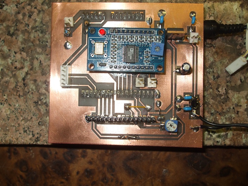
Hi Rich: I finished the Sig Gen board and it works great. The board plugs into the UNO, I hate batteries so I added a 5 volt regulated supply for the board and a 9 volt regulated supply for the UNO. Might be overkill but I can hook it up to my 12V+ bench supply and run all day. The outputs are the two 2pin connectors just below the 9850 module. The one on the right is sine wave the one on the left is connected to the square wave output (if it is ever added).
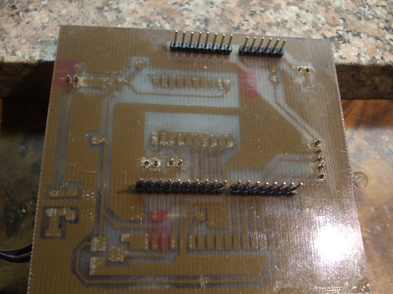
He also sent over a few photos of the finished unit. Pretty cool! Note: You won’t see the Arduino in any pics but it’s there. In fact, it’s underneath the board in the 3rd picture.
Dave has been so nice as to also provide the design and schematics he used to create his PCB. You can download the PCB design’s here. Using a laser printer and the toner-transfer method you should be able to duplicate Dave’s work. If you have any questions Dave gave me permission to post his email so go ahead and send him a note: Davewb4(at)aol.com. Obviously replace the (at) with the @ and you’re on your way.
how much out power does the uniy
I have the ardiuno board and eager to build this design
Not sure… best to ask Dave (WB4CHK) directly. He contact information is in the post above.
Rich
AD7C
I’m well into the construction phase of this board.
Had big problems with press’n'peel this time – might be my stock is old.
Anyway, found a good way of making sure the holes are correctly spaced…
Used a piece of 0.1in matrix board aligned it up carefully with the pads. Clamped it down and whizzed through the drilling phase with the generic dremel and 1mm drill bit. Adjusted the clamp for the odd aduino connector.
Anyone building this – make the contrast pot pads close together and you can use inexpensive SMD trimmers – possibly same with the other components.
I spend some time resizing the board – it didn’t reproduce with the correct sizing for our european paper sizes. A4.
Anyway, still to finish the build and test.
Hope this helps in some way.
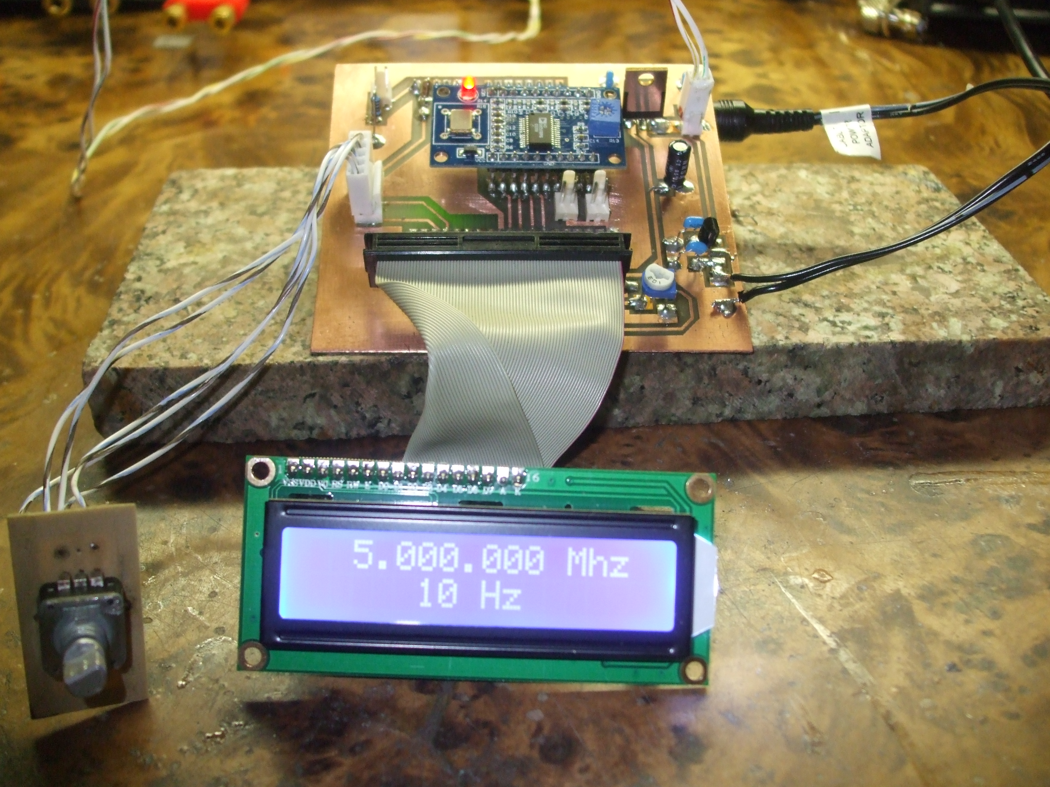
Now finished and working with a nicely formed sine wave.
Suggest to any follow on builders to use 9V regulator with a tab rather than the transistor style one. Mine is getting very hot to the touch so will be replaced.
Now to case it up and make it into my bench RF generator.
Rotary r = Rotary(2,3); // sets the pins the rotary encoder uses. Must be interrupt pins.
ad7c_vfo_i2c:31: error: “Rotary” does not name a type
can You help me ?
You did not import the rotary library correct. Simple.
Rich
AD7C
me pasa lo mismo: R = Rotary Rotary (2,3); // Establece los pines utiliza el codificador rotatorio. Debe ser pines de interrupción